 |
| Place of Origin: | Japan |
| Brand Name: | Tamagawa |
| Certification: | CE |
| Model Number: | TS5205N454 |
| Minimum Order Quantity: | 1pcs |
|---|---|
| Packaging Details: | carton |
| Delivery Time: | in stock |
| Payment Terms: | T/T, Western Union, MoneyGram |
| Supply Ability: | 100pcs/week |
| Tamagawa: | Tamagawa | TS5205N454: | TS5205N454 |
|---|---|---|---|
| Japan: | Japan | Material: | Iron |
| Color: | Black | Temperature: | 20-120 |
| Dimension: | 50mm | Wire: | Wire |
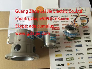
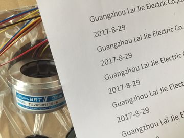
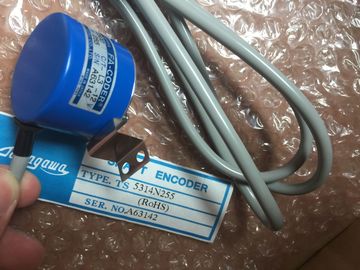
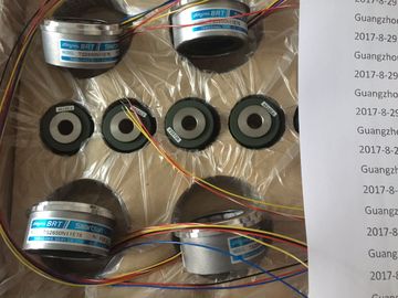
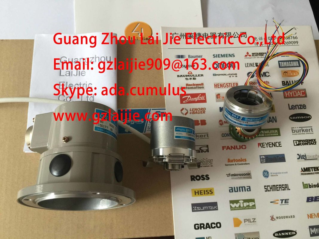
TS5205N454
Guang Zhou Lai Jie Electric Co.,LTD
Please contact with “Tommy” for the price
TS5013N60
TS5208N130
TS5246N160
TS5246N164
TS2650N1E78
TS2650N11E78
TS2650N101E78
TS5212N500
TS5308N616
TS5314N616
TS2640N671E110
TS2605N1E64
TS2640N71E10
TS4503N2000E100
TS4503N2000E200
TS5205N456
TS5205N450
TS5205N454
TS1981N56E19
TS1981N56E18
TS2651N111E78
TS2651N181E78
TS2640N321E64
TS5214N566/N8566
TS5208N8566
TS5667N120
TS5667N420
TS2651N181E78
TS2651N141E78
TS6026N151
TA8481N0300
TA8480N0100
TA8480N0200
TS5000N632
TS2014N181E32
TS2651N131E78
TS5667N420
TS5303N510
TS5246N574
TS5208N143
TS4603N1680E200
TS4603N1680E200
TA8480N0000
TS5216N579AU6802N1
TS5213N510TAMAGAWA
TS3624N22E3
TS5238N352
OIH48-2000P8-L6-5V
TS5212N530
TS5214N8566
TS5214N8566
TS5246N160
TS2620N21E11
TS2650N11E78
TS4602N1033E200
TS5668N41
TS5314N510-2500C/T
35-2000P4-L6-5V
TS5668N43
48-5000p8-L6-5V
TS5217N577
TS3641N
4509N1021E100
OIH48-2500P8-L6-5V60
TS2651N141E78
TS3653N2E5
TS5246N160
TS5246N473
OIH60-8192P24-L6-5V
TS2651N141E78
TS5667N120
TS5667N420
TS5308N616
TS3462N1E76
TS2651N1E78
TS2651N131E78
TS2014N181E32
![]()
![]()
![]()
![]()
| SIPLUS S7-300 modules can be used under extended environmental conditions. | |
| Meaning of "extended environmental conditions" |
|
| Extended temperature range of - 25 °C to + 60 °C/70°C |
Mechanical and climatic environmental conditions for
operation
Operating conditions
systems are designed for stationary use in weather-proof locations. The operating
conditions are based on the requirements of DIN IEC 60721-3-3:
● Class 3M3 (mechanical requirements)
● Class 3K3 (climatic requirements)
Use with additional measures
The may not be used under the conditions outlined below without taking additional
measures:
● at locations with a high degree of ionizing radiation
● in aggressive environments caused, for example, by
– the development of dust
– corrosive vapors or gases
– strong electric or magnetic fields
● in installations requiring special monitoring, for example
– elevators
– electrical plants in potentially hazardous areas
Mechanical environmental conditions
The table below shows the mechanical environmental conditions in the form of sinusoidal
oscillations.
Frequency band Continuous Infrequently
10 Hz ≤ f ≤ 58 Hz 0.0375 mm amplitude 0.75 mm amplitude
58 Hz ≤ f ≤ 150 Hz 0.5 g constant acceleration 1 g constant acceleration
Reducing vibrations
If your modules are exposed to severe shock or vibration, take appropriate measures
to reduce acceleration or the amplitude.
We recommend the installation of the on damping materials (for example, rubberbonded-to-metal
mounting.)
General technical data
1.4 Mechanical and climatic environmental conditions for operation
Module data
24 Manual, 06/2017, A5E00105505-AJ
Test of mechanical environmental conditions
The table below provides important information with respect to the type and scope of the test
of ambient mechanical conditions.
Condition tested Test Standard Comment
Vibration Vibration test to
IEC 60068-2-6 (sinusoidal)
Type of oscillation: Frequency sweeps with a rate of change of 1 octave/minute.
5 Hz ≤ f ≤ 9 Hz, constant amplitude 3.5 mm
9 Hz ≤ f ≤ 150Hz, constant acceleration 1 g
Duration of oscillation: 10 frequency sweeps per axis at each of three
vertically aligned axes
Shock Shock, tested to
IEC 60068-2-27
Type of shock: half-sine
Severity of shock: 15 g peak value, 11 ms duration
Direction of shock: 3 shocks in each direction (+/-) at each of three vertically
aligned axes
Climatic environmental conditions
The may be operated on following environmental conditions:
Environmental conditions Permitted range Comments
Temperature:
horizontal mounting position:
vertical mounting position:
0°C to 60°C
0°C to 40°C
-
Relative humidity 10 % to 95 % No condensation, corresponds to relative humidity
(RH) Class 2 to IEC 61131, Part 2
Barometric pressure from 1140 to 795 hPa Corresponds with an altitude of -1000 m to
2000 m
Concentration of pollutants SO2: < 0.5 ppm;
RH < 60 %, no condensation
H2S: < 0.1 ppm;
RH < 60 %, no condensation
Test: 10 ppm; 4 days
Test: 1 ppm; 4 days
ISA-S71.04 severity level G1; G2; G3 -
General technical data
1.5 Specification of dielectric tests, protection class, degree of protection, and rated voltage of
Module data
Manual, 06/2017, A5E00105505-AJ 25
1.5 Specification of dielectric tests, protection class, degree of
protection, and rated voltage of
Isolation
The isolation is designed in accordance with the requirements of EN 61131-2.
Pollution degree/overvoltage category according to IEC 61131-2: 2007
Proof of dielectric strength must be provided in the type test at a test voltage according to
IEC 61131-2:
● Pollution degree 2
● Overvoltage category: II
Protection class in accordance with IEC 61131-2: 2007
The automation system meets Protection Class I and contains parts of Protection
Classes II and III.
Degree of protection IP20
Degree of protection IP 20 in accordance with IEC 60529 for all modules of the
automation system, i.e.:
● Protection against contact with standard test finger
● Protection against foreign objects with diameters greater than 12.5 mm
● No protection against water