 |
| Place of Origin: | Japan |
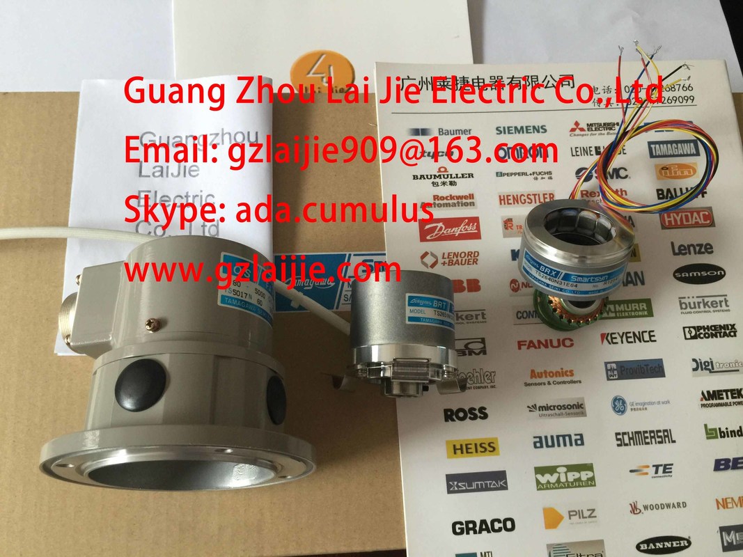
| Brand Name: | Tamagawa |
| Certification: | CE |
| Model Number: | TS2651N111E78 |
| Minimum Order Quantity: | 1pcs |
|---|---|
| Packaging Details: | carton |
| Delivery Time: | in stock |
| Payment Terms: | T/T, Western Union, MoneyGram |
| Supply Ability: | 100pcs/week |
| TAMAGAWA: | TAMAGAWA | TS2651N111E78: | TS2651N111E78 |
|---|---|---|---|
| COLOR: | GRAY | Material: | Iron |
| Temperature: | 30-120 | Dimension: | 50mm |
| Wire: | Wire |
TS2651N111E78
Guang Zhou Lai Jie Electric Co.,LTD
Please contact with “Tommy” for the price
TS3214N12
TS3214N13
TS3214N15
TS3214N16
TS3214N44
TS3218
TS3218N42
TS3218N5
TS3250E12
TS3275N125
TS3153N15E18
TS3602N213E8
TS3602N233E8
TS3602N31E8
TS3617N1E1
TS3617N1E2
TS3617N11E1
TS3617N1E3
TS3617N2E4
TS3617N2E5
TS3617N2E6
TS3617N2E7
TS3617N3E10
TS3617N3E8
TS3617N13E8
TS3617N376
TS3617N381
TS3617N3E9
TS3617N13E9
TS3617N40E3
TS3617N47E4
TS3624N1E1
TS3624N21E1
TS3624N21E2
TS3624N1E2
TS3624N102E4
TS3624N103E5
TS3624N203E5
TS3624N22E4
TS3624N23E5
TS3624N2E3
TS3624N2E4
TS3624N3E5
TS3624N3E6
TS3630N1303E9
TS3630N1309E5
TS3630N1306
TS3630N1E1
TS3630N1E2
TS3630N2E3
TS3630N2E4
TS3630N3E5
TS3630N101E2
TS3630N102E4
TS3630N22E3
TS3630N22E4
TS3631N1E1
TS3636N6
TS3641N1E1
TS3641N21E6
TS3641N22E7
TS3641N2E3
TS3641N12E3
TS3641N32
TS3641N38
TS3643N2
TS3643N212E5
TS3643N233E8
TS3653N11E2
TS3653N12E5
TS3653N13E8
TS3653N1E1
TS3653N1E2
TS3653N2E4
TS3653N2E5
TS3653N2E6
TS3653N3E7
TS3653N3E8
TS3653N3E9
TS3653N13E9
TS3653N44E8
![]()
![]()
![]()
| and are reset after restarting the module. Note |
|
| A setting through SIMATIC PDM is only possible with the use of a 6ES7322-8BH10-0AB0 as a replacement for a 6ES7322-8BH0x-0AB0 as long as the device label |
|
| 6ES7322-8BH0x-0AB0) in SIMATIC PDM was not updated with the actual device label through Device -> Load in PC/PG. |
0AB0 is used andconfigured forboth modules. No short-circuit monitoring occurs according to L+ in redundantuse.Digital modules3.24 Digital output module SM 322; DO 16 x DC 24 V/0.5 A: (6ES7322-8BH10-0AB0)Module dataManual, 06/2017, A5E00105505-AJ 149Wiring and block diagram① Status displays - greenError - red
② Channel numbers
Numbers 0 to 7 on the right side correspond to channel numbers 8 to 15③ Channel status④ Channel fault⑤ Backplane bus interfaceRedundant Output SignalsTwo clamps areon each channel. Both connections are similar and can be used for a
redundant control of an actuator. Redundant control can take place from 2 different moduleswithout an external circuit. Both signal modules must be connected to the common referencepotential M.
Digital modules
3.24 Digital output module SM 322; DO 16 x DC 24 V/0.5 A: (6ES7322-8BH10-0AB0)
Module data
150 Manual, 06/2017, A5E00105505-AJ
Technical specificationsTable 3- 22 Technical specifications SM 322; DO 16 x DC 24V/0.5ATechnical specificationsDimensions and WeightDimensions W x H x D (mm) 40 x 125 x 120Weight approx. 300 gModule-specific dataSupports isochronous mode NoNumber of outputs 16Cable length• Unshielded Max. 600 m• Shielded Max.1000 mVoltages, Currents,Potentials
Nominal load voltage L+ 24 V DC• Reverse polarity protection YesTotal current of outputs (per group)• Horizontal mounting position to 60 °C Max. 2 A• Vertical mounting position to 40 °C Max. 2 AElectrical isolation Between channels and the backplane bus Yes•n groups ofyes4Insolation tested with DC 500 V
Power consumption• From the backplane bus Max. 100 mA• From load voltage L+ (without load) Max. 100 mAPower dissipation of the module Typically 6 WStatus, Interrupts, Diagnostics
Status LEDs Green LED per channelInterrupts• Diagnostic interrupt Programmable
Diagnostic functions Programmable• Group error display Red LED (SF)• Channel error display red LED, per channel• Diagnostic information readable supportedDigital modules3.24 Digital output module SM 322; DO 16 x DC 24 V/0.5 A: (6ES7322-8BH10-0AB0)Module data
Manual, 06/2017, A5E00105505-AJ 151Technical specificationsActuator selection data
Output voltage• "1" signal Min. L + (- 0.7 V)
• "0" signal 0.7 mA * RL (RL = load resistance value)max. 31 V for RL = infiniteOutput current
• At signal "1"Nominal valuePermitted range0.5 A5 mA up to 600 mA• "0" signal (residual current) Max. 0.7mAOutput delay (with resistive load)• At "1" to "0"Max. 2.7 ms (including module cycle time)