 |
| Place of Origin: | Japan |
| Brand Name: | Tamagawa |
| Certification: | CE |
| Model Number: | TS2651N181E78 |
| Minimum Order Quantity: | 1pcs |
|---|---|
| Packaging Details: | carton |
| Delivery Time: | in stock |
| Payment Terms: | T/T, Western Union, MoneyGram |
| Supply Ability: | 100pcs/week |
| TAMAGAWA: | TAMAGAWA | TS2651N181E78: | TS2651N181E78 |
|---|---|---|---|
| Japan: | Japan | Material: | Iron |
| Color: | Black | Temperature: | 50-120 |
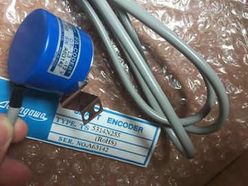
TS2651N181E78
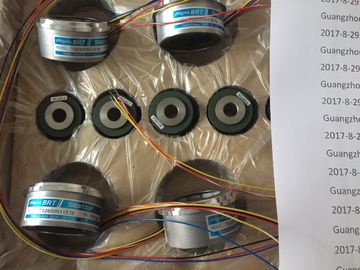
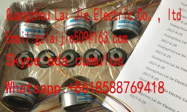
Guang Zhou Lai Jie Electric Co.,LTD
Please contact with “Tommy” for the price
TS4244N3E24
TS1983N146E5
TS3653N81E27
TS2025N471E69
TS3630N102E4
TS5017N60
TS5007N122
TS4502N1000E200
TS1983N146E5
TS3653N78E5
TS2014N181E32
TS3630N22E3
TS5108-N153-5V
TS5007N635
TS4502N1202E200
TS252N30E1
AU6270N103E63
TS3653N94E5
TS5208N141E78
TS3630N22E4
TS5146N10
TS5208N500
TS4502N2000E100
TS3503N11E43
TS3653N181E8
TS3684N1E3
TS3631N1E1
TS5146N11
TS5208N510
TS4503N1000E200
TS3062E3
TS3658N3
TS3684N13E8
TS3636N6
TS-5170-N20
TS5208N530
TS4503N1007E200
TS3092N11E12
AU6550N2062
TS3664N1E1
TS3617N1E3
TS3641N1E1
TS5207N530
TS5208N569
TS4503N1022E100
TS3095N2
AU6649N2101
TS3664N1E2
TS3630N1214E3
TS3641N21E6
TS5208N510
TS5208N576
TS4503N1022E200
TS3103N156
FACODER
TS3664N2E3
TS5013N60
TS3641N22E7
TS5208N68
TS5210N450
TS4503N1202E200
TS3103N178
TS3664N2E4
TS5013N61
TS3641N2E3
TS5212N351
TS5210N453
TS4503N1205E200
TS3103N255
TS3664N50
TS5016N60
TS3641N12E3
TS5212N510
TS5210N458
TS4503N1828E100
TS3103N302
OAH14BSD
TS3667N1E2
TS5013N63
TS3641N32
TS5213N550
TS5210N530
TS4503N2000E100
TS3103N40
![]()
![]()
![]()
![]()
| In this mode, the module changes between the two channels of each group. | |
| The four ADCs of the module simultaneously convert channels 0, 2, 4 and 6. The ADCs first convert the channels with even numbers, |
|
| and then the channels with the odd numbers 1, 3, 5 and 7 (see |
igure below.)
The channel conversion time, including module communication time, is 84 ms. The module
must change to the second channel of the group using OptoMOS relays when conversion is
completed. Opto-MOS relays require 12 ms for switching and settling. Each channel requires
a time of 97 ms, i.e. the total cycle time equals 194 ms.
Cycle time = (tK + tU) x 2
Cycle time = (84 ms + 16 ms) x 2
Cycle time = 200 ms
tC: Conversion time for one channel
tC: Channel changeover time within the channel group
8-channel mode (software filter)
Analog-to-digital conversion in this mode is identical to the conversion in 8-channel mode
(hardware filter). The four ADCs of the module simultaneously convert channels 0, 2, 4 and
6. The ADCs first convert the channels with even numbers, and then the channels with the
odd numbers 1, 3, 5 and 7 (see the figure below.)
The channel conversion time is based on the programmed interference frequency. The
channel conversion time is 32 ms, including communication time, when you set an
interference frequency of 50 Hz. The channel conversion time is 27 ms when you set an
interference frequency of 60 Hz. You can reduce channel conversion times to 9 ms by
setting an interference frequency of 400 Hz. As in "hardware filter, 8channel" mode, the
module has to toggle to the second channel of the group within a changeover time of 16 ms
using the Opto-MOS relays. The table below shows this correlation.
Table 6- 26 Cycle times in "8-channel mode (software filter)"
The converted value settles to 100% within 80 ms and is updated at intervals of 10 ms when
4-channel mode is set. The channel and module cycle times are always identical, as the
module does not change between the channels of a group: 10 ms.
Channel conversion time = channel cycle time = module cycle time = 10 ms
The wire-break monitoring software function of the module is available in all operating
modes.
The cycle time of the module is doubled in 8-channel mode (hardware or software filter),
irrespective of the number of channels at which wire-break monitoring is enabled.
In 4-channel mode (hardware filter), the module interrupts processing of input data for the
duration of 100 ms and performs a line continuity check. That is, each line continuity check
extends the module cycle time by 100 ms.
Unused channels
In order to avoid incorrect measurements, an unused channel from an active group of
channels must be configured. Connect a resistor of the nominal range to the unused channel
in order to suppress diagnostics errors.Set the "disabled" value at the "measurement type" parameter for unused channels. This
setting reduces module cycle times.Short-circuit to M or LThe module does not suffer any damage if you short-circuit an input channel to M or L.. The
channel continues to output valid data and does not report a diagnostics event.End of cycle interrupt
You can synchronize a process with the conversion cycle of the module by enabling the end
of cycle interrupt. The interrupt is set when all active channels have been converted.The table below shows the contents of the 4 bytes of additional OB40 information duringprocess or end of cycle interrupts
Certain parameters are not allowed when operating the SM 331; AI 8 x RTD analog input
module on an ET 200M PROFIBUS slave system and the PROFIBUS master is not an S7master.. Non-S7 masters do not support process interrupts. All parameters associated with
these functions are disabled for this reason. This includes process interrupt enable,
hardware restrictions and end the enabling of cycle interrupts. All other parameters areallowed.6ES7331-7PF11-0AB0
Properties