|
| Place of Origin: | Japan |
| Brand Name: | Tamagawa |
| Certification: | CE |
| Model Number: | TS2651N131E78 |
| Minimum Order Quantity: | 1pcs |
|---|---|
| Packaging Details: | carton |
| Delivery Time: | in stock |
| Payment Terms: | T/T, Western Union, MoneyGram |
| Supply Ability: | 100pcs/week |
| TAMAGAWA: | TAMAGAWA | TS2651N131E78: | TS2651N131E78 |
|---|---|---|---|
| Japan: | Japan | Material: | Iron |
| Color: | Black | Temperature: | 40-120 |
| Wire: | Wire |
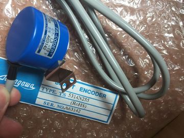
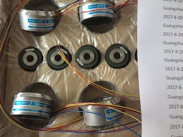
TS2651N131E78
| However, the channel conversion time is oriented on the programmed noise suppression. | |
| The channel conversion time is 76 ms, including communication time, when you set an interference frequency of 50 Hz. |
|
| he channel conversion time is 65 ms when you set an interference frequency of 60 Hz. |
Guang Zhou Lai Jie Electric Co.,LThe channel conversion time is 65 ms when you set an
interference frequency of 60 Hz.D
Please contact with “Tommy” for the price
RP-132A-T1,750PPR
ROTALY
ENCODER
RP-873ZL,2048PPR
ROTALY
ENCODER
RP-886ZN,2500PPR
ROTALY
ENCODER
RP-5354D-CD-4096PPR
ROTALY
ENCODER
RP-132A-T1,600PPR
ROTALY
ENCODER
RP-132A,2000PPR
TS2025N471E69
TS2014N181E32
TS5208N111E78
TS5208N141E78
TS3684N1E3
TS3684N13E8
TS3617N1E3
TS3617N1E1
TS3617N1E2
TS3617N2E4
TS3630N11E1
TS3664N2E4
TS3653N13E7
TS3653N12E6
TS3653N2E5
TS3624N2E3
TS3653N13E9
TS3653N2E6
TS3653N3E7
TS3653N3E8
TS3653N3E9
TS1980N43E12
TS1980N56E12
TS1981N134E9
TS1981N53E19
TS1981N56E19
TS1981N56E19
TS1982N126E6
TS1982N128E6
TS1982N53E6
TS1982N56E18
TS1983N146E5
TS252N30E1
TS3503N11E43
TS3062E3
TS3092N11E12
TS3095N2
TS3103N156
TS3103N178
TS3103N255
TS3103N302
TS3103N40
TS3132N32
TS3134N21
TS3134N22
TS3134N317
TS3134N52
TS3166
TS3166N43
TS3212N32
TS3214N12
TS3214N13
TS3214N15
TS3214N16
TS3214N44
TS3218
TS3218N42
TS3218N5
TS3250E12
You can reduce channel conversion times to 16 ms by
setting an interference frequency of 400 Hz. As in "hardware filter, 8channel" mode, the
module has to change to the second channel of the group within a changeover time of 7 ms
using The converted value settles to 100 % within 80 ms and is updated every 10 ms when 4-
channel mode is set. The channel and module cycle times are always identical, as the
module does not change between the channels of a group: 10 ms.
Channel conversion time = channel cycle time = module cycle time = 10 msthe Opto-MOS relays. The table below shows this correlation.The wire-break monitoring software function of the module is available in all operating
modes.
The 8-channel mode (hardware or software filter modes) extends module cycle times by
4 ms, irrespective of the number of channels at which wire-break monitoring is enabled.
In 4-channel mode (hardware filter), the module interrupts processing of input data for the
duration of 170 ms and performs a line continuity check. That is, each line continuity check
extends the module cycle time by 93 ms.
Unused channels
Set the "disabled" value at the "measurement type" parameter for unused channels. This
setting reduces module cycle times.
You must short-circuit all unused channels of an active group, that is, you short-circuit the
positive and negative inputs of these channels.
Effect of this measure:
● Measurement errors at the channels used of a group are avoided
● Diagnostic messages from the unused channel in a group are suppressed
Short-circuit to M or L
The module does not suffer any damage if you short-circuit an input channel to M or L.. The
channel continues to output valid data and does not report a diagnostics event.
Special features of channel groups with respect to hardware interrupts upon limit violation
You can set the high and low limits triggering hardware interrupts separately for each
channel in STEP 7.
End of cycle interrupt
You can synchronize a process with the conversion cycle of the module by enabling the end
of cycle interrupt. The interrupt is set when all active channels have been converted.
Table 6- 31 The table below shows the contents of the 4 bytes of additional OB40 information during process or end of
cycle interrupts.
.
When operating the SM 331; AI 8 xTC analog input module on an ET 200M PROFIBUS
slave system and the PROFIBUS master is not an S7 master, certain parameters are not![]()
![]()