 |
| Place of Origin: | Japan |
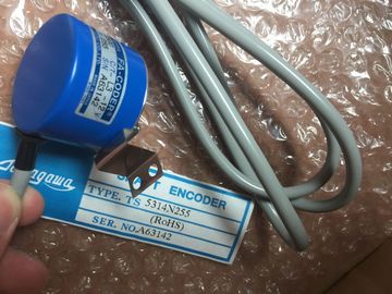
| Brand Name: | Tamagawa |
| Certification: | CE |
| Model Number: | TS5213N510 |
| Minimum Order Quantity: | 1pcs |
|---|---|
| Packaging Details: | carton |
| Delivery Time: | in stock |
| Payment Terms: | T/T, Western Union, MoneyGram |
| Supply Ability: | 100pcs/week |
| TAMAGAWA: | TAMAGAWA | TS5213N510: | TS5213N510 |
|---|---|---|---|
| Material: | Iron | Color: | Black |
| Temperature: | 30-120 | Dimension: | 50mm |
| Wire: | Wire |
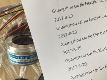
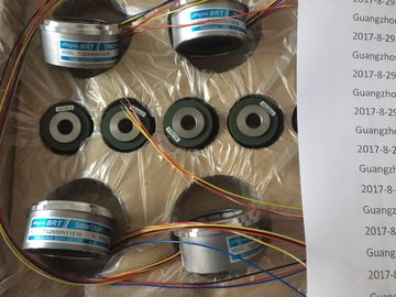
TS5213N510TAMAGAWA
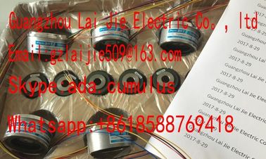
Guang Zhou Lai Jie Electric Co.,LTD
Please contact with “Tommy” for the price
OSE5KN-6-12-108
TS3674N37
TS5013N69
TS3653N13E8
TS5420
TS2640N181E100
TS4507N1205E200
TS3166N43
TS3679N2E1
TS5208N131
TS3653N1E1
TS5641N150
TS2640N321E64
TS4507N1229E200
TS3212N32
RFH102422
TS3679N3E1
TS5208N111E78
TS3617N47E4
TS1508N211
TS2650N11E78
TS4507N2000E100
TS3214N12
RFH1024-22-1M-68
TS3682N1
TS3617N1E1
TS3624N1E1
TS1508N255
TS2651N111E78
TS4507N2070E100
TS3214N13
RFH102422IM
TS3682N2
TS3617N1E2
TS3624N21E1
TS1508N257
TS26541N131E78
TS4507N2405E200
TS3214N15
TA8110N2121E802
TS3684N11E3
TS3617N2E4
TS3624N21E2
TS1508N260
TS3033N4E2
TS4507N6205E200
TS3214N16
TA8110N2121E916
TS3684N12E6
TS3630N11E1
TS3624N1E2
TS1613N200
TS3063N15E8
TS4507N8029E200
TS3214N44
TS1446N4
TS3684N13E8
TS3664N2E4
TS3624N102E4
TS16N13E12
TS3103N5037
TS4509N1002E200
TS3218
TS1508N202
TS3684N1E3
TS3653N13E7
TS3624N103E5
TS16N18E11
TS3501N
TS4509N1202E200
TS3218N42
TS1508N77
TS3684N2E6
TS3653N12E6
TS3624N203E5
TS2013N191E26
TS3510N39E10
TS4509N1831E200
TS3218N5
TS1508N85
TS3684N3E8
TS3653N2E5
![]()
![]()
![]()
![]()
| Crosstalk between outputs > 40 dB | |
| Operational limit (across entire temperature range, relative to measurement range end value in the selected output range) | |
| Voltage output |
Current output
±0.5 %
± 0.6 %
Basic error limit (operational limit at 25 °C, relative to the measurement range end value in the selected output range)
• Output voltage
• Output current
• Temperature error (relative to output range)
• Linearity error (relative to output range)
• Repeat accuracy (in transient state at 25 °C, relative to output
range)
• Output ripple; bandwidth 0 kHz to 50 kHz (relative to output
range)
± 0.4 %
± 0.5 %
± 0.002 %/K
+ 0.05 %
±0.05 %
±0.05 %
Status, interrupts, diagnostics
Interrupts
• Diagnostic interrupt programmable
Diagnostic functions
• Group error display
• Reading diagnostics information
programmable
red LED (SF)
supported
Actuator selection data
Output ranges (rated values)
• Voltage ± 10 V
0 V to 10 V
1 V to 5 V
• Current ± 20 mA
0 mA to 20 mA
4 mA to 20 mA
Load impedance (in the rated output range)
• For voltage outputs
– Capacitive load
Min. 1 kΩ
Max. 1 µF
• For current outputs
– at CMV < 1 V
– with inductive load
max. 500 Ω
max. 600 Ω
max. 10 mH
Voltage output
• Short-circuit protection
• Short-circuit current
yes
max. 25 mA
Current output
• noload voltage max. 18 V
• Destruction limit against external voltages/currents
• Voltage at outputs to MANA
• Current
max. 18 V continuous; 75 V for a duration of max. 1
s
(duty factor 1:20)
max. 50 mA d.c.
Wiring of the actuators
• for voltage output
4–wire connection
• for current output
2–wire connection
using a 40-pin front connector
supported
supported
Configuration in RUN
Special considerations must be given if you use the Configuration in RUN function.
SF LED is lit:
Status before re-configuration diagnostics on, SF LEDs lit among others (on CPU, IM or
module), although diagnostics are no longer pending and the module is operating correctly.
Solution:
● Only change the configuration when no diagnostics are pending for the module or
● Pulling and plugging the module.
6.12.1 SM 332; AO 8 x 12 Bit - Output ranges
Introduction
You can configure the outputs for operation as voltage or current outputs, or disable them.
You program the outputs at the "output type" parameter in STEP 7.
Output type "Voltage" and output range "± 10 V" are set by default at the module. You can
always use this combination of output type and range without having to program the SM 332;
AO 8 x 12 Bit in STEP 7.
Table 6- 32 Output ranges
For general information on programming analog modules, refer to the chapter Programming
analog modules (Page 294).
The table below provides an overview of configurable parameters, including defaults:
Table 6- 33 Overview of the parameters of SM 332; AO 8 x 12 Bit
Enable
• Diagnostic interrupt yes/no no dynamic Module
Diagnostics
• Group diagnostics Yes/no No static Channel
Output
• Output type
• Output range
disabled
Voltage
Current
See chapter output ranges (Page 447)
V
± 10 V
dynamic Channel
Reaction to CPU STOP ASS
HLV
Outputs zero current/voltage
Hold last value
The parameters can be set separately at each output channel of SM 332; AO 8 x 12 Bit. You
can assign separate parameters to each output channel.
Assign the parameters you set at the SFCs in the user program to the channel groups. Each
output channel of SM 332; AO 8 x 12 Bit is thus assigned to a channel group, i.e. output
channel 0 > channel group 0, for example.
Note
The output may carry invalid interim values if you modify output ranges while SM 332; AO
8 x 12 bit is in RUN.
To take unused output channels of SM 332; AO 8 x 12 Bit off power, set the "disabled"
argument at the "output type" parameter. Disabled channels do not have to be wired.
Line continuity check
SM 332; AO 8 x 12 Bit only performs a line continuity check at the current outputs.
In output ranges 0 mA to 20 mA and ± 20 mA, a "reliable" wire-break check is not possible
for output values of ± 200 µA.
Short-circuit test
SM 332; AO 8 x 12 Bit only performs a short-circuit test at the voltage outputs.
6ES7332-7ND02-0AB0
Order number: "SIPLUS S7-300 module"
6AG1332-7ND02-4AB0
Properties