TS5668N41
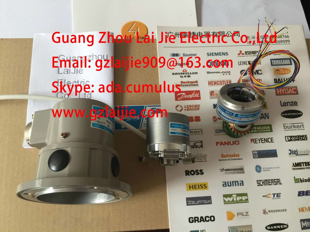
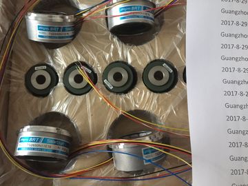
We can sell the products of Tamagawa at a Advantage price
Guang Zhou Lai Jie Electric Co.,LTD
Please contact with “Tommy” for the price
TS3624N2E3
TS3624N2E4
TS3624N3E5
TS3624N3E6
TS3630N1E1
TS3630N1E2
TS3630N2E3
TS3630N2E4
TS3630N3E5
TS3630N3E6
TS3630N1303E9
TS3630N1306
TS3630N11E1
TS3630N11E2
TS3630N12E3
TS3630N12E4
TS3630N13E5
TS3630N13E6
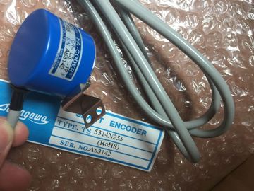
FA-CODER
TS5214N566
TS5205N450
TS5205N454
TS5205
N450
TS5205
N454
TS5205N452
TS5205
N452
TS5207
TS5208
TS5212
TS5213
TS5214
TS5231
TS5217
TS5233
TS5150
TS5300
TS5100
TS5000
TS5080
TS5170
TS5410
TS5200N500
TS5146
TS5270
TS5610
TS5620
TS1857
TS5607
TS5668N20
TS5667N120
TS5667N420
TS5645
TS5647
TS5648
TS5643
TS2223
TS2224
TS2225
TS20E12
TS13E11
TS5308N616
TS2650N11E78
TS5420N60
TS5208N131
TS3462N1E76
48-2500P8-L6-5VC/T-L3-12V
TS-5016N-60
TS5214N561
TS5214N510
TS2014N182E32
TS3653N2E5
TS5320N510
TS5016N-60
TS5016N60
TS5305N616
TS5008N12238
TS5214N564
TS5212N569
TS2651N111E78
TS2014N181E32
TS-5208N130

ed LED (SF)
Actuator selection data | |
| Output current• "1" signal | |
| Output voltage• "1" signal min. L1 (-0.8 V)Output current• "1" signal | |
ated value
Permitted range
Maximum inrush current (per group)
1 A
10 mA to 1 A
10 A (for two AC cycles)
• "0" signal (residual current) max. 2 mA
Output delay (resistive load)
• "0" to "1" transition 1 AC cycle
• "1" to "0" transition 1 AC cycle
Blocking voltage
zero transition max. 60 V
Size of the motor starter max. size 4 to NEMA
Lamp load max. 50 W
Wiring two outputs in parallel
• for redundant load control supported (only outputs of the same group)
• for performance increase not supported
Control of a digital input supported
Switching frequency
• with resistive load
• with inductive load to IEC 947-5-1, AC 15
• with lamp load
max. 10 Hz
max. 0.5 Hz
1 Hz
Short-circuit protection of the output no
Wiring of the actuators using a 20-pin* front connector
*Requires two front connectors of the appropriate version
Digital modules
3.23 Digital output module SM 322; DO 16 x DC 24 V/ 0.5 A; (6ES7322-1BH01-0AA0)
Module data
Manual, 06/2017, A5E00105505-AJ 143
3.23 Digital output module SM 322; DO 16 x DC 24 V/ 0.5 A;
(6ES7322-1BH01-0AA0)
Order number: "Standard module"
6ES7322-1BH01-0AA0
Order number: "SIPLUS module"
6AG1322-1BH01-2AA0
Properties
Properties of SM 322; DO 16 x DC 24 V/0.5 A:
● 16 outputs, electrically isolated in groups of 8
● Output current 0.5 A
● Rated load voltage 24 V DC
● Suitable for solenoid valves, DC contactors and signal lamps
Use of the module with high-speed counters
Please note when using the module in combination with high-speed counters:
Note
When using a mechanical contact to switch on the 24-V power supply to SM 322; DO
16 x DC 24 V/0.5 A, its outputs will carry "1" signal for the duration of ca. 50 µs, due to the
circuit structure.
Dimensions W x H x D (mm) 40 x 125 x 117
Weight ca. 190 g
Module-specific data
Supports isochronous mode no
Number of outputs 16
Cable length
• unshielded
• shielded
max. 600 m
max. 1000 m
Voltages, currents, electrical potentials
Rated load voltage L+ 24 V DC
Total current of outputs
(per group)
• horizontal mounting position
to 40 °C
to 60 °C
max. 4 A
max. 3 A
• vertical mounting position
to 40 °C max. 2 A
Electrical isolation
• between channels and the backplane bus yes
• between channels
in groups of
yes
8
Isolation test voltage 500 V DC
Current consumption
• from the backplane bus
• from load voltage L+ (no-load)
max. 80 mA
max. 80 mA
Power loss of the module typ. 4.9 W
Status, interrupts, diagnostics
Status display green LED per channel
Interrupts none
Diagnostic functions none
Digital modules
3.23 Digital output module SM 322; DO 16 x DC 24 V/ 0.5 A; (6ES7322-1BH01-0AA0)
Module data
146 Manual, 06/2017, A5E00105505-AJ
Technical specifications
Actuator selection data
Output voltage
• "1" signal
min. L + (- 0.8 V)
Output current
• "1" signal
Rated value
Permitted range
0.5 A
5 mA to 0.6 A
• "0" signal (residual current) Max. 0.5 mA
Output delay (resistive load)
• "0" to "1" transition max. 100 μs
• "1" to "0" transition max. 500 μs
Load resistance range 48 Ω to 4 kΩ
Lamp load max. 5 W
Wiring two outputs in parallel
• For redundant load control Supported (only outputs of the same group)
• For performance increase Not supported
Control of a digital input Supported
Switching frequency
• with resistive load max. 100 Hz
• with inductive load to IEC 947-5-1, DC 13 max. 0.5 Hz
• with lamp load max. 10 Hz
Internal limiting of the inductive shutdown voltage to typ. L + (-53 V)
Short-circuit protection of the output yes, electronic
• Threshold typ. 1 A
Wiring of the actuators using a 20-pin front connector
Digital modules
3.24 Digital output module SM 322; DO 16 x DC 24 V/0.5 A: (6ES7322-8BH10-0AB0)
Module data
Manual, 06/2017, A5E00105505-AJ 147
3.24 Digital output module SM 322; DO 16 x DC 24 V/0.5 A:
(6ES7322-8BH10-0AB0)
Order number
6ES7322-8BH10-0AB0Order number: "SIPLUS module"6AG1322-8BH10-7AB0PropertiesThe digital output module SM 322; DO 16 x DC24 V/0.5 A isdistinguished by the followingproperties:● 16 outputs, electrically isolated in groups of 4 channels● A nominal load voltage of 24 V DC● Configurable diagnostics● Programmable diagnostic interrupt● Redundant● Wire break at "0" and "1" signal● Identification Data● Firmware update possibleUse of the module with high-speed countersPlease note when using the module in combination with high-speed counters.NoteWhen using a mechanical contact to switch on the 24-V power supply to SM 322; DO16 x DC 24 V/0.5 A, its outputs will carry "1" signal for the duration of ca. 50 µs, due to thecircuit structure.Digital modules3.24 Digital output module SM 322; DO 16 x DC 24 V/0.5 A: (6ES7322-8BH10-0AB0)Module data148 Manual, 06/2017, A5E00105505-AJ
Using the module
For the use of the SM 322; DO 16 x DC24V/0.5A, the following hardware and software
requirements must be fulfilled:● For the central use in , the module can be used with all available CPUs.● For the decentral use in ET 200M, the module can be used with the following IM 153-modules and compatible successor modules:
– IM 153-2; as of 6ES7153-2BA02-0XB0, (PROFIBUS).
– IM 153-2; as of 6ES7153-2BA82-0XB0; (PROFIBUS, OUTDOOR).
– IM 153-4; as of 6ES7153-4BA0x-0XB0; (PROFINET).● Requirement: STEP 7 V5.5 (HSP0217) or higher.● A GSD file or a GSDML file must be used if the module is part of a distributed andcontrolled by a master produced by a third-party manufacturer. The corresponding file forthe selected IM 153 is available for download from the Internet(http://www..com/automation/service&support).● Module diagnosis and identification data (I&M) are available through STEP 7 and with
SIMATIC PDM as of V6.0 + SP5 (HSP0217) or SIMATIC PDM V7.0 or higher and EDDfor ET 200M "DP_IOSystem__ET200M_Module.Device" as of V1.1.12Compatible use of the module 6ES7322-8BH0x-0AB0You can repalce the digital output module 6ES7322-8BH0x-0AB0 without changing yoursettingsthrough a digital output module 6ES7322-8B10-0AB0.In this case, the module does not offer discrepancyfailure monitoring.If a STEP 7 version before STEP 7 V5.1 SP3 is used, the replacement value behaviorwillonly be entered through the parameter dialog from HW config and transferred to themoduleduringsystem startup.In this case, all other settings must be transferred through SIMATIC PDM orin theuserprogram through datasets to the module.These settings are not saved retentively on the digital output module 6ES7322-8BH10-0AB0