 |
| Place of Origin: | Japan |
| Brand Name: | Tamagawa |
| Certification: | CE |
| Model Number: | TS2651N141E78 |
| Minimum Order Quantity: | 1pcs |
|---|---|
| Packaging Details: | carton |
| Delivery Time: | in stock |
| Payment Terms: | T/T, Western Union, MoneyGram |
| Supply Ability: | 100pcs/week |
| TAMAGAWA: | TAMAGAWA | COLOR: | BLACK |
|---|---|---|---|
| Material: | Iron | Temperature: | 30-120 |
| WIRE: | WIRE | TS2651N141E78: | TS2651N141E78 |
| Dimension: | 50mm |
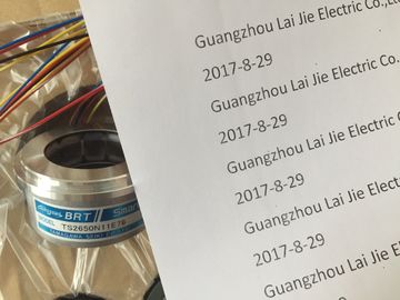
TS2651N141E78
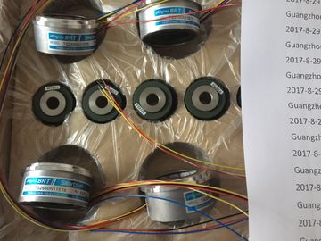
Guang Zhou Lai Jie Electric Co.,LTD
Please contact with “Tommy” for the price
TS2014N181E32
TS2014N311E32
TS2650N11E78
TS2650N1E78
TS5081N1
TS5084N250
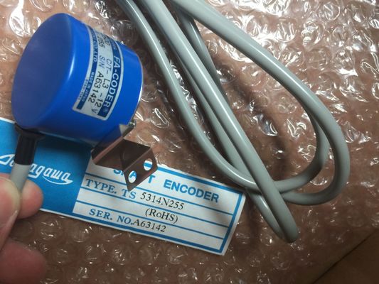
TS5314N255
TS5303N510
TS5622N131
TS1616N200
TS1501N13
TS5641N154
TS5205N454
TS5668N20
TS5667N120
TS5667N420
TS5308N616
TS3462N1E76
TS5214N561
TS5214N510
TS2014N182E32
TS3653N2E5
TS5320N510
TS5016N60
TS5016N60
TS2651N111E78
TS2014N181E32
TS5208N130
TS5214N566
TS5205N450
TS5205N454
TS2651N11E78
TS2651N141E78
TS2651N1E78
TS2651N131E78
TS5016N60
TS5013N60
TS5208N130
TS5246N160
TS5246N164
TS2650N1E78
TS2650N11E78
TS2650N101E78
TS5212N500
TS5308N616
TS5314N616
TS2640N671E110
TS2605N1E64
TS2640N71E10
TS4503N2000E100
TS4503N2000E200
TS5205N456
TS5205N450
TS5205N454
TS1981N56E19
TS1981N56E18
TS2651N111E78
TS2651N181E78
TS2640N321E64
TS5214N566/N8566
![]()
![]()
![]()
![]()
| 4 outputs in 4 channel groups | Current output |
| The output channels can be programmed as | Resolution 16 bits |
| Voltage output | Supports isochronous mode |
Supports parameter reassignment in RUN
● Programmable diagnostics and diagnostic interrupt
● Electrical isolation between:
– backplane bus interface and analog output channel
– analog output channels
– analog output and L+, M
– Backplane bus circuit and L+, M
● Supports parameter reassignment in RUN
Diagnostics
For information on diagnostic messages at the "group diagnostics" parameter, refer to
chapter Diagnostic messages of analog output modules (Page 296).
Terminal assignment
The diagrams below show various wiring options.
Note
When you switch the rated load voltage (L+) off and on, the output may carry invalid interim
values for the duration of ca. 10 ms.
Backplane bus interface
② Electrical isolation
③ Equipotential bonding
④ Functional earthing
Figure 6-44 Wiring and block diagram
Dimensions W x H x D (mm) 40 x 125 x 117
Weight ca. 220 g
Module-specific data
Supports parameter reassignment in RUN
• Reaction of non-programmed outputs
yes
return the output value which was valid before the
parameterization
Supports isochronous mode yes
Number of outputs 4
Cable length
• shielded
max. 200 m
Voltages, currents and potentials
Rated load voltage L+
• Reverse polarity protection
24 V DC
yes
Electrical isolation
• between channels and the backplane bus
• between channels and electronics power supply
• between channels
yes
yes
yes
Maximum potential difference
• between outputs (ECM)
• between MANA and Minternal (VISO)
200 V DC / 120 V AC
200 V DC / 120 V AC
Isolation test voltage 1500 V DC
Current consumption
• from the backplane bus
• from load voltage L+ (no-load)
Basic execution time of the module (independent of the number of
enabled channels)
• in standard mode
• in isochronous mode
<800 μs
750 µs
Transient recovery time
• with resistive load
• with capacitive load
• with inductive load
0.2 ms
3.3 ms
0.5 ms (1 mH) / 3.3 ms (10 mH)
Interference suppression, error limits
Crosstalk between outputs > 100 dB
Operational limit (across entire temperature range, relative to measurement range end value in the selected output range)
• Voltage output
• Current output
±0.12%
±0.18%
Basic error limit (operational limit at 25 °C, relative to the measurement range end value in the selected output range)
Linearity error (relative to output range) ±0.004%
Repeat accuracy (in transient state at 25°, relative to output range) ±0.002 %
Output ripple; range 0 Hz to 50 kHz (relative to output range) ±0.05 %
Status, interrupts, diagnostics
Interrupts
• Diagnostic interrupt programmable
Diagnostic functions
• Group error display
• Reading diagnostic information
programmable
red LED (SF)
supported
Set substitute values yes, programmable
Special considerations must be given if you use the Configuration in RUN function.
SF LED is lit:
Status before re-configuration diagnostics on, SF LEDs lit among others (on CPU, IM or
module), although diagnostics are no longer pending and the module is operating correctly.
Solution:
● Only change the configuration when no diagnostics are pending for the module or
● Pulling and plugging the module.
You can configure the outputs for operation as voltage or current outputs, or disable these.
You program the outputs at the "output type" parameter in STEP 7.
The output type "Voltage" and output range "± 10 V" are set by default at the module. You