 |
| Place of Origin: | Japan |
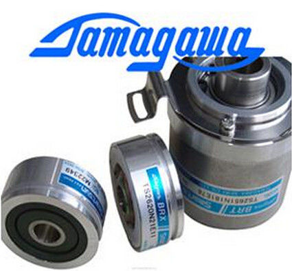
| Brand Name: | Tamagawa |
| Certification: | CE |
| Model Number: | TS5016N60 |
| Minimum Order Quantity: | 1pcs |
|---|---|
| Packaging Details: | carton |
| Delivery Time: | in stock |
| Payment Terms: | T/T, Western Union, MoneyGram |
| Supply Ability: | 100pcs/week |
| TAMAGAWA: | TAMAGAWA | Material: | Iron |
|---|---|---|---|
| Color: | Black | Temperature: | 40-100 |
| Wire: | Wire | TS5016N60: | TS5016N60 |
| Japan: | Japan | Dimension: | 40mm |
TS3653N2E5
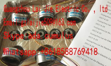
Guang Zhou Lai Jie Electric Co.,LTD
Please contact with “Tommy” for the price
TS5205N454
TS1981N56E19
TS1981N56E18
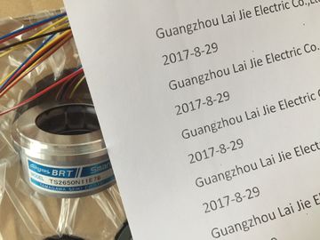
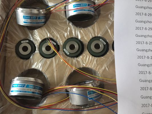
TS2651N111E78
TS2651N181E78
TS2640N321E64
TS5214N566/N8566
TS5208N8566
TS5667N120
TS5667N420
TS2651N181E78
TS2651N141E78
TS6026N151
TA8481N0300
TA8480N0100
TA8480N0200
TS5000N632
TS2014N181E32
TS2651N131E78
TS5667N420
TS5303N510
TS5246N574
TS5208N143
TS4603N1680E200
TS4603N1680E200
TA8480N0000
TS5216N579AU6802N1
TS5213N510TAMAGAWA
TS3624N22E3
TS5238N352
OIH48-2000P8-L6-5V
TS5212N530
TS5214N8566
TS5214N8566
TS5246N160
TS2620N21E11
TS2650N11E78
TS4602N1033E200
TS5668N41
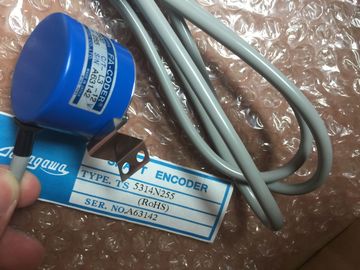
TS5314N510-2500C/T
35-2000P4-L6-5V
TS5668N43
48-5000p8-L6-5V
TS5217N577
TS3641N
4509N1021E100
OIH48-2500P8-L6-5V60
TS2651N141E78
TS3653N2E5
TS5246N160
TS5246N473
OIH60-8192P24-L6-5V
TS2651N141E78
TS5667N120
TS5667N420
TS5308N616
TS3462N1E76
![]()
![]()
![]()
| can always use this combination of output type and range without having to program the SM 332; AO 4 x 16 Bit in STEP 7. |
|
| For general information on programming analog modules, refer to the chapter Programming analog modules (Page 294). |
|
| he table below provides overview of programmable parameters and of their defau The parameters can be set separately at each output channel of SM 332; |
You
can assign separate parameters to each output channel.
Assign the parameters you set at the SFCs in the user program to the channel groups. Each
output channel of SM 332; AO 4 x 16 Bit is thus assigned to a channel group, i.e. output
channel 0 > channel group 0, for example.
Note
The output may carry invalid interim values if you modify output ranges while
SM 332; AO 4 x 16 bit is in RUN.
Reproducible reaction times (i.e. of the same length) are achieved in a SIMATIC system by
means of a constant DP bus cycle, and synchronization of the single cyclic processes
outlined below:
● Independent user program cycle. The length of the cycle time may vary due to non-cyclic
program branching.
● Independent and variable DP cycle on the PROFIBUS subnet
● Cyclic operation of the backplane bus of the DP slave.
● Cyclic signal preparation and conversion at the electronic modules of the DP slave.
The constant DP cycle runs in synchronism and at the same length. The CPU run levels
(OB61 to OB64) and isochronous IO are synchronized with this cycle. I/O data are therefore
transferred at defined and constant intervals (isochronous mode.) Maximum flutter: ±50 μs.
Requirements
● The DP master and slave must support isochronous mode. You require STEP 7 V5.2 or
higher.
During the time TO - TWA, the module reads the output data and saves the data internally.
The internal processing time for each channel is used to write the results into the individual
D/A converters.
Further information
You can find additional information on isochronous mode in the online help for STEP 7, and
in the operating instructions Distributed I/O System ET 200M.
To take unused output channels of SM 332; AO 4 x 16 Bit off power, set the "disabled"
argument at the "output type" parameter, and leave the terminal open.
Substitute values
You can configure the SM 332; AO 4 x 16 Bit for CPU STOP mode as follows: Outputs off
power, hold last value or set substitute values. The set substitute values must lie within the
output range
4 outputs in one group
● The output can be selected by individual channel
– Voltage output
– Current output
● Resolution 12 bits
● Programmable diagnostics and diagnostic interrupt
● Electrically isolated to backplane bus interface and load voltage
● Supports parameter reassignment in RUN
Diagnostics
For information on diagnostic messages at the "group diagnostics" parameter, refer to
chapter Diagnostic messages of analog output modules (Page 296).
Terminal assignment
The diagrams below show various wiring options.
Note
When you switch the rated load voltage (L+) off and on, the outputs can return incorrect
voltage/current values for the duration of about 500 ms.
The following Fig. represents the 2-wire connection with no compensation for line resistors
and the 4-wire connection with compensation for line resistors.
2-wire connection, no compensation for line resistors
② 4-wire connection, with compensation for line resistors
③ Equipotential bonding