|
| Place of Origin: | Japan |
| Brand Name: | Tamagawa |
| Certification: | CE |
| Model Number: | TS5246N473 |
| Minimum Order Quantity: | 1pcs |
|---|---|
| Packaging Details: | carton |
| Delivery Time: | in stock |
| Payment Terms: | T/T, Western Union, MoneyGram |
| Supply Ability: | 100pcs/week |
| TAMAGAWA: | TAMAGAWA | Material: | Iron |
|---|---|---|---|
| Color: | Black | Temperature: | 30-100 |
| TS5246N473: | TS5246N473 | Dimension: | 40mm |
| Wire: | Wire |
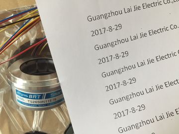
TS5246N473
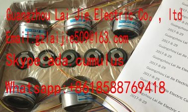
Guang Zhou Lai Jie Electric Co.,LTD
Please contact with “Tommy” for the price
RP-112A-T1,750PPR
ROTALY
ENCODER
RP-112A-T1,1500PPR
ROTALY
ENCODER
RP-112A-T1,3000PPR
ROTALY
ENCODER
RP-132,1500PPR
ROTALY
ENCODER
RP-446Z,750PPR
ROTALY
ENCODER
M-52004
RP872ZL
2048PPR
ROTALY
ENCODER
RP-132A-T1,750PPR
ROTALY
ENCODER
RP-873ZL,2048PPR
ROTALY
ENCODER
RP-886ZN,2500PPR
ROTALY
ENCODER
RP-5354D-CD-4096PPR
ROTALY
ENCODER
RP-132A-T1,600PPR
ROTALY
ENCODER
RP-132A,2000PPR
TS2025N471E69
TS2014N181E32
TS5208N111E78
TS5208N141E78
TS3684N1E3
TS3684N13E8
TS3617N1E3
TS3617N1E1
TS3617N1E2
TS3617N2E4
TS3630N11E1
TS3664N2E4
TS3653N13E7
TS3653N12E6
TS3653N2E5
TS3624N2E3
TS3653N13E9
TS3653N2E6
TS3653N3E7
TS3653N3E8
TS3653N3E9
TS1980N43E12
TS1980N56E12
TS1981N134E9
TS1981N53E19
TS1981N56E19
TS1981N56E19
TS1982N126E6
TS1982N128E6
TS1982N53E6
TS1982N56E18
TS1983N146E5
TS252N30E1
![]()
![]()
![]()
![]()
| Electrically isolated to backplane bus interface and load voltage | |
| Supports parameter reassignment in RUN Diagnostics |
|
| For information on diagnostic messages at the "group diagnostics" parameter, refer to chapter Diagnostic messag2-wire connection: no compensation for line impedance |
4-wire connection: with compensation for line impedance
③ Equipotential bonding
④ Functional earthing
⑤ Internal supply
⑥ Electrical isolation
⑦ Backplane bus interface
⑧ Analog-to-Digital Converter (ADC)
Figure 6-48 Wiring and block diagrames of analog output modules
Destruction limit against external voltages/currents
• Voltage at outputs to MANA
• Current
max. 18 V continuous;
75 V for the duration of max. 1 s (duty factor 1:20)
max. 50 mA DC
• Wiring of the actuators
• for voltage output
– 2-wire connection
– 4-wire connection (measuring line)
• for current output
– 2-wire connection
using a 20-pin front connector
supported
supported
supported
Reassigning parameters in RUN
If you reassign parameters in RUN, the following special characteristic applies.
SF LED is lit:
If a diagnostics was pending prior to reconfiguration, the SF LEDs (on CPU, IM or module)
may be lit even though diagnostics is no longer pending and the module is operating
correctly.
Solution:
● Only assign new parameters if no diagnostics is pending, or
● unplug module and plug it in again.
6.15.1 Output ranges of SM 332; AO 2 x 12 Bit
Introduction
You can configure the outputs for operation as voltage or current outputs, or disable them.
You program the outputs at the "output type" parameter in STEP 7.
Output type "Voltage" and output range "± 10 V" are set by default at the module. You can
always use this combination of output type and range without having to program the SM 332;
AO 2 x 12 Bit in STEP 7.
Output ranges
Program the voltage and current output ranges in STEP 7.
Table 6- 38 Output ranges of SM 332; AO 2 x 12 Bit
The parameters can be set separately at each output channel of SM 332; AO 2 x 12 Bit. You
can assign separate parameters to each output channel.
Assign the parameters you set at the SFCs in the user program to the channel groups. Each
output channel of SM 332; AO 2 x 12 Bit is thus assigned to a channel group, i.e. output
channel 0 > channel group 0, for example.
Note
The output may carry invalid interim values if you modify output ranges while SM 332; AO
2 x 12 bit is in RUN.
To take unused output channels of SM 332; AO 2 x 12 Bit off power, set the "disabled"
argument at the "output type" parameter. Disabled channels do not have to be wired.
Line continuity check
SM 332; AO 2 x 12 Bit only performs a line continuity check at the current outputs.
In output ranges 0 mA to 20mA and ±20 mA, a "reliable" wire-break check is not possible for
output values of-20s to ±200 µA.
Short-circuit test
SM 332; AO 2 x 12 Bit only performs a short-circuit test at the voltage outputs.
Substitute values
You can configure the SM 332; AO 2 x 12 Bit for CPU STOP mode as follows: Outputs off
power, hold last value or set substitute values. The set substitute values must lie within the
output range.
ES7334-0CE01-0AA0
Properties
● 4 inputs in one group and 2 outputs in one group
● Resolution 8 bits
Programmable measurement type at each channel group
– Voltage
– Current
● Not programmable, measurement and output type defined by hardwiring
● Connected to potential of the backplane bus interface
● Electrically isolated to load voltage
Terminal assignment
The diagrams below show various wiring options.
Note
Note when wiring the SM 334:
• analog ground MANA(terminal 15 or 18) is interconnected with chassis ground M of the
CPU or interface module IM. Use a cable with a conductor cross-section of at least
1 mm2.
The module will shut down if the ground connection between MANA and M is missing.
Inputs are read with 7FFFH, and outputs return a value of 0. The module may be
destroyed if operated without ground over a longer period of time.
• the supply voltage for the CPU and/or the interface module (IM) may not be connected
with reversed polarity. Reverse polarity will inevitably lead to the destruction of the
module, because MANA develops an impermissible high potential (+24 V.)
Internal supply
② Analog-to-Digital Converter (ADC)
③ Inputs: Current measurement with 4-wire transducer
④ Outputs: Voltage output
⑤ Digital-to-Analog Converter (DAC)
⑥ Backplane bus interface
⑦ Equipotential bonding
⑧ Functional earthing
Figure 6-51 Wiring and block diagrams
• Resolution (including overshoot range) 8 bits
Conversion time (per channel)
• programmable
• Conversion time in µs
no
<500
Basic execution time of outputs max. 5 ms
Transient recovery time
• with resistive load
• with capacitive load
• with inductive load
0.3 ms
3.0 ms
0.3 ms
Interference frequency suppression, error limits for inputs
Interference frequency suppression at F = n (f1 ± 1 %) (f1 = interference frequency)
• Common mode interference (Vpp < 1 V) > 60 dB
Crosstalk between outputs > 50 dB
Operational limit (across entire temperature range, relative to measurement range end value in the selected input range)
• Voltage input
• Current input
± 0,9 %
± 0,8 %
Basic error limit (operational limit at 25 °C, relative to measurement range end value of the selected input range)
• Voltage input
• Current input
± 0,7 %
± 0,6 %
Temperature error (relative to input range) ± 0.005 %/K
Linearity error (relative to input range) ± 0,05 %
Repeat accuracy (in transient state at 25 °C, relative to input range) ± 0,05 %
Output ripple; range 0 Hz to 50 kHz (relative to output range) ± 0,05 %
Interference frequency suppression, error limits of outputs
Crosstalk between outputs > 40 dB
Operational limit (across entire temperature range, relative to measurement range end value in the selected output range)
• Voltage output
• Current output
± 0,6 %
± 1,0 %
Basic err
Basic error limit (operational limit at 25 °C, relative to the measurement range end value in the selected output range)
• Voltage output
• Current output
± 0,5 %
± 0,5 %
Temperature error (relative to output range) ± 0.02 %/KLinearity error (relative to output range) ± 0,05 %Repeat accuracy (in transient state at 25 °C, relative to output range) ± 0,05 %
Output ripple (bandwidth relative to output range) ± 0,05 %Status, interrupts, diagnosticsInterrupts noneDiagnostic functionsInput ranges (rated values) / input impedance• Voltage• Current0 V to 10 V/100 k Ω
0 mA to 20 mA/50 Ω
Maximum voltage at voltage input (destruction limit) max. 20 V continuous; 75 V for max. duration of 1 s
(duty factor 1:20)
Maximum current at current input (destruction limit) 40 mA
Wiring of the signal sensors
for voltage measurement• for current measurement
as 2-wire transducer
as 4-wire transducerusing a 20-pin front connectorsupportedsupported with externalupplyActuator selection dataOutput ranges (rated values)• Voltage• Current0 V to 10 V0 mA to 20 mALoad impedance (min. 5 kΩmax. 1 µFmax. 300 Ωmax. 1 mHVoltageoutput• Short-circuit protection• Short-circuit currentyesmax. 11 mA
Current output• noload voltage max. 15 VDestruction limit against external voltages/currents
• Voltage at outputs to MANA• Currentmax. 15 V, continuousmax. 50 mA d.c.Wiring of the actuators
• for voltage output2-wire connection
4-wire connection (measuring line)using a 20-pin front connectorsupported
not supported
SM 334; AI 4/AO 2 x 8/8 bit is a non-isolated analog IO module. SM 334; AI 4/AO 2 x 8/8 Bitis notprogrammable.AddressingThe I/O of the module are addressed beginning at the module start address.The address of a channel is derived from the module start address and an address offset.
3 Module start address + 6 bytes address offset
SM 334; AI 4/AO 2 x 8/8 Bit is not programmable.Defining the measurement and output type
Set the measurement type (voltage, current) by hardwiring the input channel.Set the output type (voltage, current) by hardwiring the output channel.See also
Representation of the values for analog input channels (Page 262)
Representation of analog values for analog output channels (Page 279)
Analog modules
6.16 Analog IO module SM 334; AI 4/AO 2 x 8/8 Bit; (6ES7334-0CE01-0AA0)
S7-300 Module data
Manual, 06/2017, A5E00105505-AJ 483
6.16.3 Measurement and output ranges of SM 334; AI 4/ AO 2 x 8/8 bit
Measuring ranges
SM 334; AI 4/AO 2 x 8/8 Bit provides the 0 V to 10 V and 0 mA to 20 mA measuring ranges.
By contrast to the other analog modules, the SM 334 has a lower resolution and no negative
measuring ranges. Make allowances for this feature when reading the measured value
tables Analog value representation in the ± 1 V to ± 10 V measuring ranges and Analog
value representation in the 0 mA to 20 mA and 4 mA to 20 mA measuring ranges.