|
| Place of Origin: | Japan |
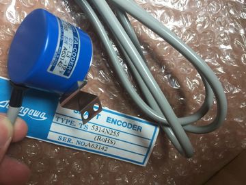
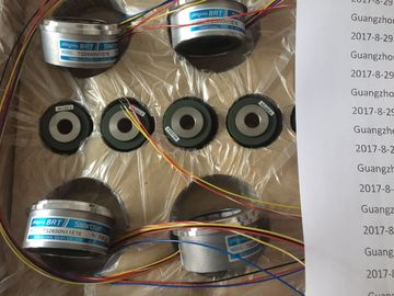
| Brand Name: | Tamagawa |
| Certification: | CE |
| Model Number: | TS2651N1E78 |
| Minimum Order Quantity: | 1pcs |
|---|---|
| Packaging Details: | carton |
| Delivery Time: | in stock |
| Payment Terms: | T/T, Western Union, MoneyGram |
| Supply Ability: | 100pcs/week |
| TAMAGAWA: | TAMAGAWA | Material: | Iron |
|---|---|---|---|
| Color: | Black | Dimension: | 50mm |
| TS2651N1E78: | TS2651N1E78 | Temperature: | 30-80 |
| Wire: | Wire |
TS2651N1E78
| TS2651N1E78 | Enable • Diagnostic interrupt yes / n |
| Enable parameter | Enable parameter. |
| Applies to all 3 channels | Applies to all 3 channels. |
Guang Zhou Lai Jie Electric Co.,LTD
Please contact with “Tommy” for the price
TS4507N2405E200
TS3214N15
TA8110N2121E802
TS3684N11E3
TS3617N2E4
TS3624N21E2
TS1508N260
TS3033N4E2
TS4507N6205E200
TS3214N16
TA8110N2121E916
TS3684N12E6
TS3630N11E1
TS3624N1E2
TS1613N200
TS3063N15E8
TS4507N8029E200
TS3214N44
TS1446N4
TS3684N13E8
TS3664N2E4
TS3624N102E4
TS16N13E12
TS3103N5037
TS4509N1002E200
TS3218
TS1508N202
TS3684N1E3
TS3653N13E7
TS3624N103E5
TS16N18E11
TS3501N
TS4509N1202E200
TS3218N42
TS1508N77
TS3684N2E6
TS3653N12E6
TS3624N203E5
TS2013N191E26
TS3510N39E10
TS4509N1831E200
TS3218N5
TS1508N85
TS3684N3E8
TS3653N2E5
TS3624N22E4
TS2014N181E32
TS3653N95E8
TS4509N2002E200
TS3250E12
TS1526N55
TS3692N103
TS3624N2E3
TS3624N23E5
TS2014N311E32
TS3617N2E7
TS4509N2405E200
TS3275N125
TS1562N102
TS3692N41
TS3653N13E9
TS2014N18E32
TS2014N312E32
TS3617N3E10
TS4509N7000E100
TS3153N15E18
TS1567N132
TS3692N42
TS3653N2E6
TS2014N43E31
TS2018N303E51
TS3617N3E8
TS4514N1021E200
TS3602N213E8
TS3699N112
TS3653N3E7
TS2058N21E1-A
TS20E12
TS3617N13E8
TS4514N1407E200
TS3602N233E8
TS1857N16
TS4603N1532E200
Absolute value encoder (SSI)
1)
none; 13 bits; 21 bits; 25 bits none: The encoder input is switched off.
Code type 1) Gray; Binary Code returned by the encoder.
Baud rate 1.3) 125 kHz; 250 kHz; 500 kHz; 1 MHz Data transfer rate of the SSI position detection.
Observe the relationship between cable lengths
and the transmission rate (refer to chapter
"Technical data of SM 338; POS-INPUT
(Page 512)")
Monoflop time 1),2),3) 16 µs; 32 µs; 48 µs; 64 µs The monoflop time represents the minimum interval
between two SSI frames.
The configured monoflop time must be greater
than the monoflop time of the absolute value
encoder.
Scaling
• Places
• Steps per revolution 4
0 to 12
2 to 8192
Scaling right-aligns the encoder value in the address
space; irrelevant places are discarded.
Enabling the Freeze function off; 0; 1 Definition of the digital input that initiates freezing
of the encoder value at the positive edge.
1 Refer to the technical specifications of the absolute value encoder
2 The monoflop time represents the interval between two SSI frames. The configured monoflop
time must be greater than the monoflop time of the absolute value encoder (see the
technical data of the manufacturer). The time 2 x (1 / transmission rate) is added to the
value set in HW Config. A transmission rate of 125 kHz and configured monoflop time of
16 µs sets an effective monoflop time of 32 µs.
3 Restriction of the monoflop time of the absolute value encoder:
(1 / transmission rate) < monoflop time of the absolute value encoder < 64 µs + 2 x (1 /
transmission rate)
4 to powers of two
Please note that in asynchronous mode, the transmission rate and monoflop time affect the
accuracy and update quality of the encoder values. In isochronous mode, the transmission
rate and monoflop time have an influence on the accuracy of the freeze function.
The SM 338 inputs and outputs are addressed beginning at the module start address. The
input and output address is determined in your configuration of SM 338 in STEP 7.
In the double data word from channel 0, the status of digital input I0 is reported to bit 27
(digital input status) and the double data word from channel 1 is reported to digital input I1.
In the double data word from channel 2, the bit is always = 0.
You can read the data areas in your user program using the STEP 7 operation L PED "xyz."
Example of access to encoder values and use of the freeze function
You want to read and evaluate the values at the encoder inputs. The module start address is
256.
You can then process the encoder values from the bit memory address areas MD 100, MD
104 and MD 108. The encoder value is set in bits 0 to 30 of the memory double word.
The SM 338 provides diagnostics messages, i.e. it always provides all diagnostics messages
without user intervention.
Reactions to a diagnostic message in STEP 7
Actions initiated by diagnostic messages:
● The diagnostic message is entered in the diagnosis of the module and forwarded to the
CPU.