 |
| Place of Origin: | Japan |
| Brand Name: | Tamagawa |
| Certification: | CE |
| Model Number: | TS5013N60 |
| Minimum Order Quantity: | 1pcs |
|---|---|
| Packaging Details: | carton |
| Delivery Time: | in stock |
| Payment Terms: | T/T, Western Union, MoneyGram |
| Supply Ability: | 1000pcs/week |
| TAMAGAWA: | TAMAGAWA | Material: | Iron |
|---|---|---|---|
| TS5013N60: | TS5013N60 | Japan: | Japan |
| COLOR: | BLACK | Temperature: | 40-120 |
| Dimension: | 50mm |
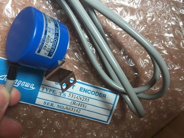
TS5013N6
We can sell the products of Tamagawa at a Advantage price
Guang Zhou Lai Jie Electric Co.,LTD
Please contact with “Tommy” for the price
TS3250E12
TS1526N55
TS3692N103
TS3624N2E3
TS3624N23E5
TS2014N311E32
TS3617N2E7
TS4509N2405E200
TS3275N125
TS1562N102
TS3692N41
TS3653N13E9
TS2014N18E32
TS2014N312E32
TS3617N3E10
TS4509N7000E100
TS3153N15E18
TS1567N132
TS3692N42
TS3653N2E6
TS2014N43E31
TS2018N303E51
TS3617N3E8
TS4514N1021E200
TS3602N213E8
TS3699N112
TS3653N3E7
TS2058N21E1-A
TS20E12
TS3617N13E8
TS4514N1407E200
TS3602N233E8
TS1857N16
TS4603N1532E200
TS2058N21EAA
TS20N2E11
TS3617N376
TS4514N1828E200
TS3602N31E8
TS-1905N146E6
TS4603N1700E200
TS2087N12E9
TS2142N1E63
TS3617N381
TS4514N2002E200
TS3617N1E1
TS1922N3
TS4603N2002E200
TS2097N1E9
TS2151N1E26
TS3617N3E9
TS4514N2405E200
TS3617N1E2
TS2014N181E32
TS4603N7002E200
TS4602N6321E100
TS3617N2E4
TS3617N13E9
TS4515N1202E200
TS3617N11E1
TS2014N182E32
TS1505N55
TS4515N6000E200
TS4603N1000E100
TS3617N2E5
TS3617N40E3
Internal module cycle time between the backplane bus and the output
driver input
• "0" to "1" transition 0.1 µs to 20 µs
• "1" to "0" transition 0.1 µs to 20 µs
Load resistance range 48 Ω to 4 kΩ![]()
![]()
![]()
![]()
| between channels | between channels and the backplane bus 170 V DC, 120 V AC |
| in groups of | between channels and electronics power supply 170 V DC, 120 V AC |
| aximum potential difference | between outputs of different groups 170 V DC, 120 V AC |
Lamp load max. 5 WWiring two outputs in parallel• For redundant load control Supported (only outputs of the same group)
• For performance increase Not supported
Control of a digital input Supported
Switching frequency• with resistive load max. 1000 Hz• with inductive load to IEC 947-5-1, DC 13 max. 0.5 Hz
• with lamp load max. 10 Hz
Internal limiting of the inductive shutdown voltage to typ. L + (-53 V)
Short-circuit protection of the output yes, electronic
• Threshold typ. 1 A
Wiring of the actuators using a 20-pin front connector
6ES7322-5GH00-0AB0
Properties
Performance features of the SM 322; DO 16 x UC24/48 V digital output module:
● 16 electrically isolated semiconductor relay outputs
● Electrical isolation between channels of 120 V● Switching characteristics: RDS ON is typically 0.25 Ohm, and RDS OFF is typically greater
than 100 GOhm● Designed for load voltages up to 48 V AC or DC, no minimum load voltage
● Designed for output loads up to 0.5 A, no minimum load current● Outputs are fully independent and support any wiring configuration
● Set substitution values or "Hold last values" can be programmed at the outputs for CPUSTOP.● The module supports diagnostics of programming errors and of external power failure
● Suitable for AC solenoids, actuators, motor starters, FHP motors and signal lamps● Supports parameter rea
Dimensions W x H x D (mm) 40 x 125 x 117
Weight ca. 260 g
Module-specific data
Supports parameter reassignment in RUN Yes
• Reaction of non-programmed outputs Return the output value which was valid before the
parameterization
Supports isochronous mode no
Number of outputs 16
Cable length
• unshielded• shielded
max. 600 mmax. 1000 mDimensions and weight
Voltages, currents, electrical potentialsRated electronics supply voltage L + 24 V DC
• Reverse polarity protection• Power failure bufferingyes
min. 5 msTotal current of outputs (per group)
• horizontal mounting positionup to 60 °C
max. 0.5 A• other mounting positions
o 40 °C
max. 0.5 ACumulated current of outputs (per module)• horizontal mounting position
to 60 °Cmax. 8 A• other mounting positionsto 40 °C
max. 8 AElectrical isolation
• between channels and the backplane bus yes
• between channels and electronics power supply yes
between outputs of different groups 1500 V AC
Current consumption
• from the backplane bus
• from supply voltage L+
max. 100 mA
max. 200 mA
Power loss of the module typ. 2.8 W
Status, interrupts, diagnostics
Status display green LED per channel
Diagnostic functions
• Group error display red LED (SF)
Interrupts
• Diagnostic interrupt
• Reading diagnostics information
programmable
supported
Output voltage
• "1" signal min. L+ (-0.25 V)
Output current
• Rated inrush current (per group) with "1" signal
• "0" signal (residual current)
0.5 A max. 1.5 A (max. 50 ms)
max. 10 μA
Output delay (resistive load)
• "0" to "1" transition
• "1" to "0" transition
max. 6 ms
max. 3 ms
External fuse for relay outputs Fuse, I2 t :1 A2 s, fast-blow fuse*
Lamp load max. 2.5 W
Internal parallel wiring of 2 outputs Varistor, 85 V
• for redundant load control
• for performance increase
supported
not supported
Control of a digital input supported
Switching frequency
• with resistive load max. 10 Hz
• with inductive load to IEC 947-5-1; DC 12 AC/12 max. 0.5 Hz
• with lamp load max. 0.5 Hz
Wiring of the actuators using a 40pin front connector
* Outputs must be protected by a 250 V fast-blow fuse (recommended fuses: Wickman
194-1100 1.1 A and Littlefuse 0217-800 V 800 mA.)
When mounted in a hazardous area to National Electric Code (NEC), always remove the
fuse when the module is outside of the potentially explosive atmosphere, and use a suitable
tool.
Configuration in RUN
Special considerations must be given if you use the Configuration in RUN function.
SF LED is lit:
Status before re-configuration diagnostics on, SF LEDs lit among others (on CPU, IM or
module), although diagnostics are no longer pending and the module is operating correctly.
Solution:
● Only change the configuration when no diagnostics are pending for the module or
● Pulling and plugging the module
Parameters of digital output module SM 322 DO 16 x UC24/48 V
Programming
The tables below show data record numbers for static and dynamic parameters.
Table 3- 24 Data record 0 (static parameters):
Parameters Comment
Enable diagnostics Enabling an interrupt as a reaction to module failure caused by faulty
parameter, hardware error, or voltage error.
Table 3- 25 Data record 1 (dynamic parameters):
Parameters Comment
Reaction to CPU STOP
Hold last value
Substitute value output
Substitute value
Substitute value Each bit represents an output
This module supports fail state/substitution value outputs when the CPU changes from RUN
to STOP.
Status displays
Each output of this module is equipped with a green LED to indicate the relay state. In
addition, a red LED (SF) indicates the diagnostics status of the module.
Diagnostics, troubleshooting
Diagnostics data are assigned according to the technical data listed below.
The four system diagnostics data bytes can be read in the additional interrupt information as
data record 0, or in the first 4 bytes of data record 1.
Structure of the data record and system diagnostics for SM 322 DO 16x UC 24/48V
Structure of data record 1:
Table 3- 26 Structure of the data record for SM 322 DO 16 x UC 24/48 V
Data record 1 byte address
Available information Contents
0..3 System-specific diagnostics data 4 bytes
Module fault yes
D1: Internal fault yes
D2: External fault yes
D3: Channel fault no
D4: External auxiliary voltage missing yes
D5: Front connector missing no
D6: Module not programmed yes
D7: Incorrect parameters yes
System diagnostics byte 2:
D0..D3: Module class 1111
D4: Channel information available no
D5: User information available no
D6: Diagnostics interrupt from substitute no
D7: Reserve
System diagnostics byte 3:
D0: Wrong/missing memory module no
D1: Communication error noD2: RUN/STOP operating state noD3: Watchdog timeout yes
D4: Internal power failure noD5: Battery 1 low noD6: Backup system failure no
D7: Reserve
System diagnostics byte 4:
D0: Rack failure noD1: Processor failure yes
D2: EPROM fault yesD3: RAM fault yes
D4: DAC error noD5: Fuse blown noD6: Process interrupt lost noD7: ReserveProperties of digital output module SM 322; DO 16 x AC120/230 V/1 A:● 16 outputs, fused and electrically isolated in groups of 8
● Output current 1 A● Rated load voltage 120/230 VAC
● Suitable for AC solenoids, actuators, motor starters, FHP motors and signal lamps
Channel number
② Status LEDs - greenError LED - red
③ Backplane bus interfaceDimensions W x H x D 40 x 125 x 117Weight ca. 275 g
Module-specific dataSupports isochronous mode No
Number of outputs 16Cable length
• unshielded
• shielded
max. 600 m
max. 1000 m
Voltages, currents, electrical potentialsLoad voltage L1All load voltages must be connected to the same phase120/230 VAC
Total current of outputs (per group)• horizontal mounting positionto 40 °C
to 60 °C
max. 4 A
max. 2 A
• vertical mounting positionto 40 °C
max. 2 AElectrical isolation
• between channels and the backplane bus yes• between channels
in groups of
yes8Maximum potential difference• between Minternal and outputs 230 VAC
• between outputs of different groups 500 VAC
Isolation test voltage 4000 VDC
Current consumption
• from the backplane bus
• from load voltage L+ (no-load)
max. 200 mA
max. 2 mA
Power loss of the module typ. 8.6 W
Status, interrupts, diagnostics
Status display green LED per channel
Interrupts
• Diagnostic interrupt no
Diagnostic functions
• Group error display
ed LED (SF)(fuse or no L1/N)Output voltage• "1" signal– At maximum current– At minimum currentmin. L 1 (- 1.5 V)min. L 1 (- 8.5 V)
Output current
• "1" signal
Rated value
Permitted range at 0 °C to 40 °C
Permitted range at 0°C to 60°CMaximum inrush current (per group)1 A
10 mA to 1 A10 mA to 0.5 A0 A (two half-waves)• with "0" signal (residual current) max. 2 mA
Blocking voltage max. 60 V
Zero transition
Size of the motor starter max. size 4 to NEMA
Lamp load max. 50 W
Wiring two outputs in parallel
• for redundant load control supported (only outputs of the same group)
• for performance increase noControl of a digital input supportedSwitching frequency• with resistive load
• with inductive load to IEC 947-5-1, AC 15max. 10 Hzmax. 0.5 Hz• with lamp load max. 1 Hz
Short-circuit protection of the output Fuse 8 A,250 V; per group• Fuse-tripping current min. 40 A
• Response time max. 300 msReplacement fuses 8 A fuse, fast-blowing• Wickman
• Schurter
• Littlefuse19 194-8 A
SP001.1014217.008
Fuse holder
• Wickman 19 653Wiring of the actuators using a 20-pin front connectorDigital output module SM 322; DO 8 x DC 24 V/2 A;(6ES7322-1BF01-0AA0)
Order number
6ES7322-1BF01-0AA0
Properties
Properties of SM 322; DO 8 x DC 24 V/2 A:● 8 outputs, electrically isolated in groups of 4