 |
| Place of Origin: | Japan |
| Brand Name: | Tamagawa |
| Certification: | CE |
| Model Number: | TS5013N61 |
| Minimum Order Quantity: | 1pcs |
|---|---|
| Packaging Details: | carton |
| Delivery Time: | in stock |
| Payment Terms: | T/T, Western Union, MoneyGram |
| Supply Ability: | 100pcs/week |
| Tamagawa: | Tamagawa | TS5013N61: | TS5013N61 |
|---|---|---|---|
| Japan: | Japan | COLOR: | BLACK |
| Material: | Iron | Wire: | Wire |
| Temperature: | 20-120 | Dimension: | 30-120 |
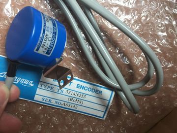
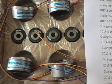
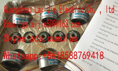
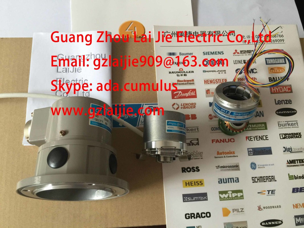
TS5013N61
Guang Zhou Lai Jie Electric Co.,LTD
Please contact with “Tommy” for the price
TS4603N7002E200
TS4602N6321E100
TS3617N2E4
TS3617N13E9
TS4515N1202E200
TS3617N11E1
TS2014N182E32
TS1505N55
TS4515N6000E200
TS4603N1000E100
TS3617N2E5
TS3617N40E3
TS4515N2405E200
TS3617N1E3
TS2014N185E32
TS4602N1000E200
TS4603N1000E200
TS3617N2E6
TS5214N566
TS5205N450
TS5213N551
TS5208N122
TS5208N23
TS5778N171
TS5210N53
TS5320N510
TS5000N632
TS5212N510
TS5213N510
TS5312N616
TS208N101
TS5208N130
TS5213N530
TS5013N68
TS5214N566
TS5200N500
TS5305N616
TS5669N220
TS5214N564
TS5246N158
TS5667N650
TS5213N551
TS5668N20
TS5667N120
TS5667N420
TS5246N160
TS5312N512
TS5208N122
TS5641N151
TS5270N15
TS5308N616
TS5213N510
TS2014N181E32
TS5308N616
TS3462N1E76
TS5214N561
TS5214N510
TS2014N182E32
TS3653N2E5
TS5320N510
TS5016N-60
TS5016N60
TS2651N111E78
TS2014N181E32
TS2651N131E78
TS2651N141E78
TS5214N566
![]()
![]()
![]()
![]()
| Contact in output current circuit | |
| Inductive reactance needs a protective circuit | |
| Figure 3-1 Relay contact for emergency stop in output current circuit Digital modules |
3.5 How to protect digital modules from inductive overvoltage
Module data
62 Manual, 06/2017, A5E00105505-AJ
Configuration of coils operated with direct current
Coils operated with direct current are shown in the following diagram and configured with
diodes or Z diodes.
① with diode
② with Z diode
Figure 3-2 Configuration of coils operated with direct current
Properties of the diode/Z diode circuit:
● Cut-off currents can be avoided. Z diode withstands a higher cut-off voltage.
● High cut-off delay (6 to 9 times higher compared to non-protective cid´rcuits).
Faster cut-off of the Zener diode compared to the diode circuit.
Connection of AC-operated coils
The operation of AC coils with varistors or RC elements is shown in the diagram
① with varistor
② with RC element
Figure 3-3 Connection of AC-operated coils
Properties of a circuit with varistor:
● The amplitude of the cut-off current is limited but not attenuated.
● The steepness of the overvoltage remains the same.
● Low cut-off delay.
Properties of acircuit with RC elements:
● Reduction of the amplitude and steepness of the cut-off current.
● Low cut-off delay.
Digital modules
3.6 Digital input module SM 321; DI 64 x DC 24 V, sinking/sourcing; (6ES7321-1BP00-0AA0)
Module data
Manual, 06/2017, A5E00105505-AJ 63
3.6 Digital input module SM 321; DI 64 x DC 24 V, sinking/sourcing;
(6ES7321-1BP00-0AA0)
Order number
6ES7321-1BP00-0AA0
Properties
Properties of SM 321; DI 64 x DC 24 V, Sinking/Sourcing:
● 64 inputs, isolated in 4 groups of 16
● Rated input voltage 24 V DC
SM321; DI 64 X DC 24 V Sinking/Sourcing features two terminal blocks for connecting
actuators and sensors to the module front connector. A connecting cable is used to establish
the module connections.
64-channel I/O modules are integrated with the HSP 2019 V 1.0. The HSP forms part of
STEP 7 V 5.4 SP2 and can be installed from STEP 7 V 5.4 and higher.
GSD/GSDML files
The 64-channel I/O modules are supported by the ET 200M versions listed below. Download
the corresponding GSD/GSDML files from the following link: on the Internet
To search for PROFIBUS GSD files, type in the entry ID 113498.
● To search for PROFINET GSDML files, type in the entry ID: 25057900.
PROFIBUS
● IM 153-1, as of 6ES7153-1AA03-0XB0, E12 with GSD file SI01801D.*, version V 1.5
● IM 153-2, as of 6ES7153-2BA02-0XB0, E01 with GSD file SI04801E.*, version V 1.0
PROFINET
● IM 153-4 PN, as of 6ES7153-4AA00-0XB0 with GSDML file version V 2.1
If the station is configured with STEP 7, you can use the SM 321 digital input module with all
CPUs in the following tables. Startup cannot be performed if no configuration is loaded.
This module must be configured in a STEP 7 project in which the correct address
assignment and allocation of the input/output point is ensured. Using the module without
having first carried out this configuration work can lead to machines or processes operating
in an unexpected manner.
If machines or processes do run in an unexpected manner, this can result in death, serious
injury, and/or material damage.
6ES7321-1BL00-0AA0
Order number: "SIPLUS module"
6AG1321-1BL00-2AA0
Properties
Properties of SM 321; DI 32 x DC 24 V:
● 32 inputs, isolated in groups of 16
● Rated input voltage 24 V DC
● Suitable for switches and 2-/3-/4-wire proximity switches (BEROs)
6ES7321-1EL00-0AA0
Properties
Properties of SM 321; DI 32 x AC 120 V:
● 32 inputs, electrically isolated in groups of 8
● Rated input voltage 120 VAC
● Suitable for switches and 2-/3-wire AC proximity switches
6ES7321-1BH02-0AA0
Order number: "SIPLUS module"6AG1321-1BH02-2AA0PropertiesProperties of SM 321; DI 16 x DC 24 V:● 16 inputs, electrically isolated in groups of 16● Rated input voltage 24 V DC● suitable for switches and 2- /3-/4-wire proximity switches(BEROs)Technical specificationsDimensions and weightDimensions W x H x D (mm) 40 x 125 x 117Weight ca. 200 gModule-specific dataSupports isochronous mode noNumber of inputs 16Cable length• unshielded• shieldedmax. 600 mmax. 1000 mVoltages, currents, electrical potentialsNumber of simultaneously controlled inputs
• horizontal mounting positionto 60 °C
• vertical mounting positionto 40 °C16
16Electrical isolation• between channels and the backplane bus• between channels• in groups ofyesyes16Isolation test voltage 500 V DCCurrent consumption
• from the backplane bus max. 10 mA
Power loss of the module typ. 3.5 WStatus, interrupts, diagnosticsStatus display green LED per channelInterrupts noneDiagnostic functionsnoneEncoder selection dataInput voltage• Rated value• "1" signal• "0" signal24 V DC
13 V to 30 V- 30 V to + 5 VInput current• "1" signal typ. 7 mA
nput delay• "0" to "1" transition "1" to "0" transition1.2 ms to 4.8 ms1.2 ms to 4.8 msInput characteristics to IEC 61131, type 1Connection of 2-wire BEROs• Permissible quiescent currentsupportedmax. 1.5 mAWiring of the signal transmitters using a 20-pin front connectorDigital input module SM 321; DI 16 x DC 24 V High Speed;(6ES7321-1BH10-0AA0)
Order number6ES7321-1BH10-0AA0PropertiesProperties of SM 321; DI 16 x DC 24 V High Speed:
● 16 inputs, electrically isolated in groups of 16
● Rated input voltage 24 V DC
● suitable for switches and 2- /3-/4-wire proximity switches (BEROs)
● Supports isochronous mode
Wiring and block diagram of SM 321; DI 16 x DC 24 V High Speed