|
| Place of Origin: | Japan |
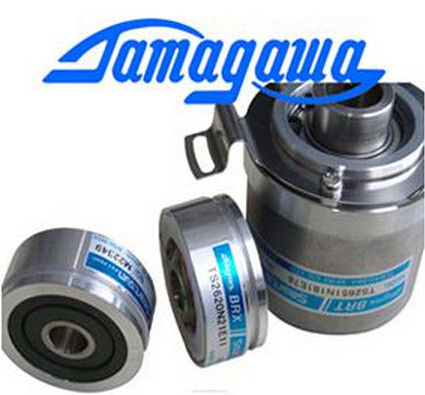
| Brand Name: | Tamagawa |
| Certification: | CE |
| Model Number: | TS5013N64 |
| Minimum Order Quantity: | 1pcs |
|---|---|
| Packaging Details: | carton |
| Delivery Time: | in stock |
| Payment Terms: | T/T, Western Union, MoneyGram |
| Supply Ability: | 100pcs/week |
| TAMAGAWA: | TAMAGAWA | TS5013N64: | TS5013N64 |
|---|---|---|---|
| COLOR: | BLACK | Temperature: | 30-120 |
| Material: | Iron | Dimension: | 50mm |
| Wire: | Wire |
TS5013N64
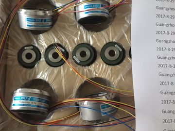
Guang Zhou Lai Jie Electric Co.,LTD
Please contact with “Tommy” for the price
TS2651N181E78
TS2651N141E78
TS6026N151
TA8481N0300
TA8480N0100
TA8480N0200
TS5000N632
TS2014N181E32
TS2651N131E78
TS5667N420
TS5303N510
TS5246N574
TS5208N143
TS4603N1680E200
TS4603N1680E200
TA8480N0000
TS5216N579AU6802N1
TS5213N510TAMAGAWA
TS3624N22E3
TS5238N352
OIH48-2000P8-L6-5V
TS5212N530
TS5214N8566
TS5214N8566
TS5246N160
TS2620N21E11
TS2650N11E78
TS4602N1033E200
TS5668N41
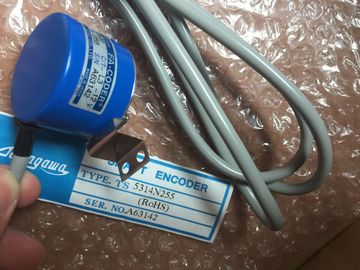
TS5314N510-2500C/T
35-2000P4-L6-5V
TS5668N43
48-5000p8-L6-5V
TS5217N577
TS3641N
4509N1021E100
OIH48-2500P8-L6-5V60
TS2651N141E78
TS3653N2E5
TS5246N160
TS5246N473
OIH60-8192P24-L6-5V
TS2651N141E78
TS5667N120
TS5667N420
TS5308N616
TS3462N1E76
TS2651N1E78
TS2651N131E78
TS2014N181E32
TS3103N40
TS3653N2E5
TS3653N3E8
TS3684N1E3
TS3684N2E6
TS3684N3E8
TS3667N3E8
TS3624N2E3
TS3624N2E4
TS3624N3E6
TS3630N1E1
TS3630N2E3
TS3630N1306
TS3630N1303E9
TS3630N1214E3
TS5013N60
TS5013N61
TS5016N60
TS5013N63
TS5013N64
TS5016N61
![]()
![]()
![]() Repeat accuracy (in settled state at 25 °C, relative to measurement
Repeat accuracy (in settled state at 25 °C, relative to measurement![]()
| Linearity error | Repeat accuracy (in settled state at 25 °C, relative to measurement |
| Voltage input • Current input |
|
| Temperature error |
ange end value in the input range)
Interrupts
• Hardware interrupt when limit value is exceeded
• Hardware interrupt at end of cycle
• Diagnostic interrupt
Programmable channels 0 to 7
programmable
programmable
Diagnostic functions programmable
• Group error display
• Reading diagnostic information
red LED (SF)
supported
Input range (rated values) / input impedance
• Voltage ± 5 V / 2 MΩ
1 V to 5 V / 2 MΩ
± 10 V / 2 MΩ
• Current 0 mA to 20 mA / 250 Ω
4 mA to 20 mA / 250 Ω
± 20 mA / 250 Ω
Maximum voltage at voltage input (destruction limit) 35 V continuous; 75 V for max. duration of 1 s (duty
factor 1:20)
Maximum current at current input (destruction limit) 40 mA
Wiring of the signal transmitters using a 40pin front connector
• for voltage measurement
• for current measurement
as 2-wire transducer
as 4-wire transducer
supported
possible, with separate transducer supply
supported
1) Interference frequency for 4-channel mode is "All"
2) Interference frequencies 50/60/400 Hz are designated as "All"
3) The series mode rejection in 8-channel mode is reduced as follows:
50 Hz > 70 db
60 Hz > 70 db
400 Hz > 80 dB
50/60/400 Hz > 90 dB
4) In 4-channel mode, the converted value settles to 100% within 80 ms. The value determined in this process is returned
at intervals of max. 10 ms.
If you reassign parameters in RUN, the following special characteristic applies.
SF LED is lit:
If a diagnostics was pending prior to reconfiguration, the SF LEDs (on CPU, IM or module)
may be lit even though diagnostics is no longer pending and the module is operating
correctly.
Solution:
● Only assign new parameters if no diagnostics is pending, or
● unplug module and plug it in again.
The measurement type and range is configured at the "measuring type" parameter in
STEP 7.
Table 6- 9 Measurement types and ranges
Selected type of measurement Output range
Voltage V: ± 5 V, from 1 V to 5 V, ± 10 V
Current (4-wire transducer)
4DMU
0 mA to 20 mA
4 mA to 20 mA
± 20 mA
Channel groups
The channels of SM 331; AI 8 x 16 bits are arranged in four groups of two channels. You
always assign parameters to a group. The interrupt limits form the exception.
The table below shows the relevant configuration of channel groups. The channel group
number is required to program SFC parameters in the user program.
Table 6- 10 Assignment of SM 331; AI 8 x 16 Bit channels to channel groups
Channels ... ...form one channel group each
Channel 0 Channel group 0
Channel 1
Channel 2 Channel group 1
Channel 3
Channel 4 Channel group 2
Channel 5
Channel 6 Channel group 3
Channel 7
For information on programming analog modules, refer to the chapter Programming analog
modules (Page 294).
Operating modes of SM 331; AI 8 x 16 Bit:
● 8-channel mode
● 4-channel mode
8-channel operating mode
In this mode, the module changes between the two channels of each group. Since the
module contains four analog/digital converters (ADC), all four ADCs convert simultaneously
for channels 0, 2, 4 and 6. After converting the channels with the even numbers, all ADCs
simultaneously convert for the channels with the odd numbers 1, 3, 5 and 7 (see the figure
below).The channel conversion time is based on the programmed noise suppression. The channel
conversion time is 76 ms, including communication time, at a set interference frequency of
50 Hz. The channel conversion time is 65 ms when you set an interference frequency of
60 Hz. You can reduce channel conversion times to 16 ms by setting an interference
frequency of 400 Hz. When you set 50, 60 and 400 Hz , the channel conversion time
amounts to 88 ms. The module then has to switch to a different channel of the group by
means of the OptoMOS relay. Opto-MOS relays require 7 ms for switching and settling. The
following table shows this relationship.In this mode, the module does not change between the channels of the groups. The four
ADCs of the module simultaneously convert the channels 0, 2, 4 and 6.The converted value settles to 100% within 80 ms and is updated every 10 ms when 4-
channel mode is set. The channel and module cycle times are always identical, because the
module does not change between the channels of a group: 10 ms.
Channel conversion time = channel cycle time = module cycle time = 10 msSet the "disabled" value at the "measuring method" parameter for unused channels. This
setting reduces module cycle times.
As certain programmed inputs may remain unused due to the channel group configuration in
8-channel mode, make allowances for the special features of these inputs outlined below to
activate the diagnostics functions at the channels being used:
● Measuring range 1 V to 5 V: wire the used input and unused input of the same channel
group in parallel.
● Current measurement, 4 to 20 mA: Connect unused input in series to the input of the
same channel group. A shunt resistor must be connected for each programmed and
unused channel.
● Other measuring ranges: Short-circuit the plus and minus inputs of the channel.The wire break test is available for the voltage measuring range 1 to 5 V and the current
measuring range 4 to 20 mA.
When there is a configured measuring range of 1 to 5 V or 4 to 20 mA and the wire break
test is activated, the analog input module reports a wire break in the diagnostics when
underflow (-32768) is reached.
● The module also triggers a diagnostic interrupt if this function is enabled in the program.