 |
| Place of Origin: | Japan |
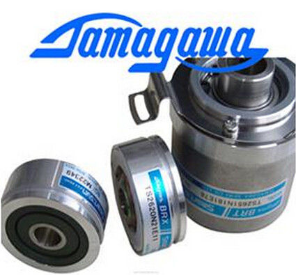
| Brand Name: | Tamagawa |
| Certification: | CE |
| Model Number: | TS5016N64 |
| Minimum Order Quantity: | 1pcs |
|---|---|
| Packaging Details: | carton |
| Delivery Time: | in stock |
| Payment Terms: | T/T, Western Union, MoneyGram |
| Supply Ability: | 100pcs/week |
| TAMAGAWA: | TAMAGAWA | TS5016N64: | TS5016N64 |
|---|---|---|---|
| Material: | Iron | Color: | Black |
| Temperature: | 40-120 | Wire: | Wire |
| Dimension: | 40mm |
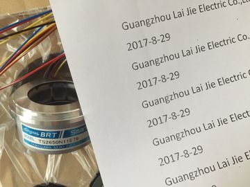
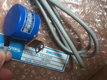
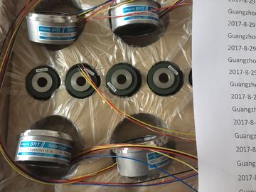
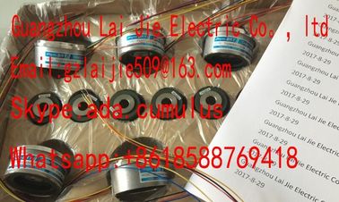
TS5016N64
Guang Zhou Lai Jie Electric Co.,LTD
Please contact with “Tommy” for the price
TS3630N1303E9
TS3630N1309E5
TS3630N1306
TS3630N1E1
TS3630N1E2
TS3630N2E3
TS3630N2E4
TS3630N3E5
TS3630N101E2
TS3630N102E4
TS3630N22E3
TS3630N22E4
TS3631N1E1
TS3636N6
TS3641N1E1
TS3641N21E6
TS3641N22E7
TS3641N2E3
TS3641N12E3
TS3641N32
TS3641N38
TS3643N2
TS3643N212E5
TS3643N233E8
TS3653N11E2
TS3653N12E5
TS3653N13E8
TS3653N1E1
TS3653N1E2
TS3653N2E4
TS3653N2E5
TS3653N2E6
TS3653N3E7
TS3653N3E8
TS3653N3E9
TS3653N13E9
TS3653N44E8
TS3653N4E12
TS3653N14E12
TS3653N58E5
TS3653N65E27
TS3653N81E27
TS3653N78E5
TS3653N94E5
TS3653N181E8
TS3658N3
TS3664N1E1
TS3664N1E2
TS3664N2E3
TS3664N2E4
TS3664N50
TS3664N50
TS3667N1E2
TS3667N11E2
TS3667N2E5
TS3667N2E6
TS3667N3E7
TS3667N3E8
TS3667N13E8
TS3674N37
TS3679N2E1
TS3679N3E1
TS3682N1
TS3682N2
TS3684N11E3
![]()
![]()
![]()
| External load voltage missing | Faulty parameters transferred to module Check the measuring range module |
| Load voltage L+ of module missing Connect supply | Program the module |
| Configuration / programming | Common-mode error Potential difference CMV between inputs Mand |
the reference potential of measuringcircuit (MANA out of limits)
Connect M- with MANAWirebreak Resistance of transducer circuit too high Use a different type of sensor, or modify thewiring, for example, using a larger conductor
cross-section.Open circuit between module and sensor Connect the cableChannel not connected (open) Disable the channel group ("measuring method"
parameter)Wire the channel
Underflow Input value below undershoot range; possiblecause of error:
wrong measuring range settingprogram a different measuring range
polarity reversal of the sensor wiring in themeasuring ranges 4 to 20 mA and 1 to 5 V
Check the connectionsOverflow Input value exceeds overshoot range program a different measuring rangeExternal load voltage missing
Load voltage L+ of module missing Connect supply L+
Configuration / programming
error
Faulty parameters transferred to module
Assign new module parameters
Short-circuit to M Overload at output Eliminate overload
Short-circuit at output QV to MANA Eliminate the short-circuit
Wirebreak Actuator impedance too high Use a different type of actuator, or modify the wiring
using cables with a larger conductor cross-section
Wire-break between the module and
actuator
Connect the cable
Channel not used (open) Disable the channel group ("output type" parameter)
This section describes the interrupt response of analog modules. Always distinguish
between the following interrupts:
● Diagnostic interrupt
● Hardware interrupt
Note that certain analog modules do not support interrupts, or are only partially capable of
"handling" the interrupts described below. For information on modules which support
interrupt functionality, refer to their technical data.
Description of the STEP 7 blocks
For detailed information on the OBs and SFCs mentioned below, refer to the STEP 7 Online
Help.
Enabling interrupts
There are no default interrupt settings, that is, interrupts are disabled if not set accordingly.
Program the interrupt enable parameter in STEP 7.
Incoming error events (initial occurrence) and outgoing error events (error is cleared) are
reported by means of diagnostic interrupt, if this interrupt is enabled.
The CPU interrupts user program execution in order to process diagnostic interrupt OB82.
You can call SFC51 or 59 in OB82 in the user program to view details of diagnostics data
output by the module.
Diagnostics data remain consistent until the program exits OB82. The program
acknowledges the diagnostic interrupt at the module when it exits OB82.
Hardware interrupt with "high or low limit exceeded" trigger
Define a working range by setting a high and low limit. If the process signal (for example, the
temperature) overshoots this working range, the module triggers a hardware interrupt,
provided the interrupt is enabled.
The CPU interrupts user program execution in order to execute hardware interrupt OB40.
In the user program of OB 40, you can define the reaction of the automation system to the
violation of limits
The program acknowledges the diagnostic interrupt at the module when it exits OB40.
Note
Note: the system does not generate a hardware interrupt if your limit setting exceeds the
overshoot or undershoot range.
You can synchronize a process with the cycle of the analog input module by programming a
hardware interrupt trigger at the end of the cycle.
One cycle comprises the conversion of the measured values of all active channels of the
analog input module. The module processes the channels in successive order. After all
measured values were successfully converted, the module outputs an interrupt to the CPU in
order to report new measured values at its channels.
You can always use this interrupt to download the actual converted analog values.
This chapter describes:
1. Analog module selection and commissioning sequence
2. Overview of essential module properties
3. Modules which are available (properties, connection and block diagrams, technical data
and additional information on the module):
a) for analog input modules
b) for analog output modules
c) for analog IO modules
You can use FC105 "SCALE" (scale values) and FC106 "UNSCALE" (unscale values)
blocks to read and output analog values in STEP 7. Those FCs are available in the STEP 7
standard library, in the "TI-S7-Converting Blocks" subfolder
You should be familiar with the structure of the parameter sets (data records 0, 1 and 128) in
system data before you edit module parameters in the STEP 7 user program.
You should be familiar with the structure of diagnostics data (data records 0, 1) in system
data before you edit any diagnostics data of the module in the STEP 7 user program.
See also
Principles of programming signal modules in the user program (Page 522)
Evaluating diagnostic data of signal modules in the user program
The table below contains the steps required to successfully complete commissioning of
analog modules.
You do not strictly have to adhere to this suggested sequence, that is, you can complete
other tasks such as installing or commissioning other modules, or program the module at an
earlier or later time.
1. Selecting the module
2. For certain analog input modules: Set the measuring type and range using the measuring
range module
3. Installing the module in the SIMATIC S7 system
4. Assigning module parameters
5. Connect the measuring transducers or loads to the module
6. Commission the configuration
7. Analyze the configuration if commissioning failed
See the "Installation" and "Commissioning" chapter in the Installation Manual for your
automation system:
● S7-300 Automation System, Installation or
● S7-400 Automation System, Installation or
● Distributed I/O Device ET 200M