|
| Place of Origin: | Japan |
| Brand Name: | Tamagawa |
| Certification: | CE |
| Model Number: | TS5017N60 |
| Minimum Order Quantity: | 1pcs |
|---|---|
| Packaging Details: | carton |
| Delivery Time: | in stock |
| Payment Terms: | T/T, Western Union, MoneyGram |
| Supply Ability: | 100pcs/week |
| TAMAGAWA: | TAMAGAWA | TS5017N60: | TS5017N60 |
|---|---|---|---|
| Japan: | Japan | Color: | Black |
| Material: | Iron | Temperature: | 40-120 |
| Wire: | Wire | Dimension: | 40mm |
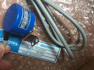
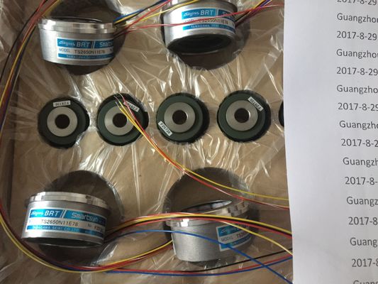
TS5017N60
Guang Zhou Lai Jie Electric Co.,LTD
Please contact with “Tommy” for the price
TS3674N37
TS3679N2E1
TS3679N3E1
TS3682N1
TS3682N2
TS3684N11E3
TS3684N12E6
TS3684N13E8
TS3684N1E3
TS3684N2E6
TS3684N3E8
TS3692N103
TS3692N41
TS3692N42
TS3699N112
TS3699N172
TS3699N232
TS3738N1E7
TS3738N1E7
TS3741N3E8
TS374
TS3762N15E4
TS4126N1017E235
TS4127N1017E215
TS4127N1017E235
TS4231N6E17
TS4231N6E17
TS4244N10E24
TS4244N3E24
TS4502N1000E200
TS4502N1202E200
TS4502N2000E100
TS4503N1000E200
TS4503N1007E200
TS4503N1022E100
TS4503N1022E200
TS4503N1202E200
TS4503N1205E200
TS4503N1828E100
TS4503N2000E100
TS4503N2070E100
TS4503N2202E200
TS4503N2036E501
TS4506N1202E200
TS4507N1002E200
TS4507N1202E200
TS4507N1205E200
TS4507N1229E200
TS4507N2000E100
TS4507N2070E100
TS4507N2405E200
TS4507N6205E200
TS4507N8029E200
TS4509N1002E200
TS4509N1202E200
TS4509N1831E200
TS4509N2002E200
TS4509N2405E200
TS4509N7000E100
TS4514N1021E200
TS4514N1407E200
TS4514N1828E200
![]()
![]()
![]()
![]()
| You can wire and connect the following transducers to the analog input modules, depending | Current transducers |
| on the type of measurement | As 2-wire transducer |
| Voltage transducers | As 4-wire transducer |
Resistors
● Thermocouples
Cables for analog signals
Always use shielded twisted-pair cables to wire analog signals. This reduces interference.
Connect both ends of the analog cable shield to ground.
Any potential difference between the cable ends may cause an equipotential current on the
shield and disturbance on analog signals. Avoid this effect by means of low-impedance
equipotential bonding. Ground only one end of the shielding.
Electrically isolated analog input modules
Electrically isolated analog input modules are not electrically interconnected at the reference
point of the measuring circuit (MANA and/or M) and the M terminal of the CPU/IM153.
Always use electrically isolated analog input modules if there is any risk of potential
difference VISO developing between the reference point of measuring circuit (MANA and/or
M-) and the M terminal of the CPU/IM153 .
You can prevent the potential difference V ISO from exceeding limits by means of
equipotential interconnection of terminals MANA and M of the CPU/IM153.
Non-isolated analog input modules
Non-isolated analog input modules require a low-impedance connection between the
reference point of measuring circuit MANA and the M terminal of the CPU or interface module
IM 153. Interconnect terminals MANA with M of the CPU or interface module IM 153. Any
potential difference between MANA and M of the CPU or interface module IM 153 may corrupt
the analog signal.
Limited potential difference CMV
The permissible potential difference UCM (CMV/Common Mode) may not be exceeded. A
CMV fault may develop between
● the measurement inputs (M+ / M-) and the reference potential of measuring circuit MANA
● between the measuring inputs.
The following diagrams show the measures to be taken when wiring transducers.
Electrically isolated transducers are not connected to local ground potential. They can be
operated in electrically isolated mode.
Potential differences may develop between electrically isolated sensors. These potential
differences may be caused by interference, or may develop as a result of the local
distribution of transducers.
In environments with a high level of EMC interference, it is advisable to interconnect M- with
MANA in order to prevent the permissible CMV value from being exceeded.
Note
For modules where VCM ≤ 2.5 V, interconnect M- and MANA (see the diagrams below)
Do not interconnect M- with MANA when wiring and connecting 2-wire transducers and
resistance transducers. An equalization current develops at the interconnection of M- with
MANA and corrupts the measured value. This also applies to unused inputs which are
programmed accordingly.
4.2.2 Wiring non-isolated transducers
Non-isolated transducer
Non-isolated transducers are interconnected with local ground potential. Always interconnect
MANA with local ground when using non-isolated transducers.
Local conditions or interference may cause potential differences CMV (static or dynamic)
between locally distributed measuring points. If the maximum CMV value is exceeded,
interconnect the measuring points by means of equipotential conductors
When connecting non-isolated transducers to electrically isolated modules, the CPU / IM 153
can be operated in grounded or ungrounded mode.
Always operate the CPU / IM 153 in grounded mode if you connect non-isolated transducers
to non-isolated modules.
You may not connect non-isolated 2-wire transducers/resistive transducers to non-isolated
analog inputs!
This chapter describes how to wire and connect voltage transducers and and the
corresponding items to be observed.
This chapter describes the wiring and connecting of current transducers and rules to be
observed.
Supported current transducers
● As 2-wire transducer
● As 4-wire transducer
necting 2-wire transducers with power supply from the module
The 2-wire transducer is wired to the short circuit-proof supply voltage at the terminals of the
analog input module.
The 2-wire transducer converts the process variable into a current. 2-wire transducers must
be electrically isolated.
4-wire transducers are connected to a separately power supply
This chapter describes the wiring and connecting of resistance thermometers and resistors
and rules to be observed.
Supported resistance transducers
● With 4-wire connection
● With 3-wire connection
● With 2-wire connection
The module provides a constant current at terminals IC+ and IC- for current measurements.
The constant current is fed to the resistance for measuring its voltage potential. The constant
current cables must be wired directly to the resistance thermometer/resistor.
Measurements programmed for 4-or 3-wire connections compensate for line resistance and
return considerably higher precision compared to 2-wire connections.
Measurements with programmed 2-wire connections also record line impedance in addition
to their internal resistance.
4-wire connection of a resistance thermometer
The voltage generated at the resistance thermometer is measured across the M+ and Mterminals.Observe the correct polarity when wiring and connecting the devices (IC+ and M+,
and IC - and M- at the resistance thermometer).
Always wire and connect the IC+, M+, IC- and M- lines directly to the resistancethermometer.
When connecting 3-wire devices to modules equipped with four terminals, you should
generally bridge M- and IC-. Always wire and connect the connected C+ and M+ lines directlyto the resistance thermometer.
The image shows the basic wiring. Please observe the notes in the description about the
respective module.For 2-wire connections, insert a bridge between the M+ and IC+ and between the M- and ICterminals
of the module. The line impedance is included in the measurement.
This chapter describes the wiring and connecting of thermocouples and corresponding rulesto be observed.
The figure below shows several thermocouples and their temperature ranges.
Thermocouples consist of a pair of thermal probes and all necessary installation and
connecting parts. The thermocouple pair consists of two wires made of different metals, or of
metal alloys soldered or welded together at their ends.
The different thermocouple types, for example, K, J or N, are derived from different material