 |
| Place of Origin: | Japan |
| Brand Name: | Tamagawa |
| Certification: | CE |
| Model Number: | TS5420N60 |
| Minimum Order Quantity: | 1pcs |
|---|---|
| Packaging Details: | carton |
| Delivery Time: | in stock |
| Payment Terms: | T/T, Western Union, MoneyGram |
| Supply Ability: | 100pcs/week |
| TAMAGAWA: | TAMAGAWA | TS5420N60: | TS5420N60 |
|---|---|---|---|
| COLOR: | BLACK | Material: | Iron |
| Temperature: | 40-120 | WIRE: | WIRE |
| Dimension: | 40mm |
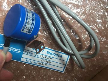
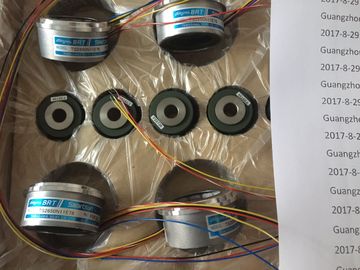
TS5420N60
Guang Zhou Lai Jie Electric Co.,LTD
Please contact with “Tommy” for the price
TS5210N553
TS3684N1E3
TS3684N2E6
TS3684N3E8
TS3684N11E3
TS3684N12E6
TS3684N13E8
TS3617N1E3
TS3617N1E1
TS3617N1E2
TS3617N2E4
TS3617N2E5
TS3617N2E6
TS3617N2E7
TS3617N3E8
TS3617N3E9
TS3617N3E1
TS3617N11E3
TS3617N11E1
TS3617N11E2
TS3617N12E4
TS3617N12E5
TS3617N12E6
TS3617N12E7
TS3617N13E8
TS3617N13E9
TS3617N13E1
TS3653N1E1
TS3653N1E2
TS3653N1E3
TS3653N2E4
TS3653N2E5
TS3653N2E6
TS3653N3E7
TS3653N3E8
TS3653N3E9
TS3653N11E1
TS3653N11E2
TS3653N11E3
TS3653N12E4
TS3653N12E5
TS3653N12E6
TS3653N13E7
TS3653N13E8
TS3653N13E9
TS3103N40
TS3641N1E1
TS3641N2E3
TS3641N11E1
TS3641N12E3
TS3664N1E1
TS3664N1E2
TS3664N2E3
TS3664N2E4
TS3664N11E1
TS3664N11E2
TS3664N12E3
TS3664N12E4
TS3667N1E1
TS3667N1E2
TS3667N2E4
TS3667N1E3
TS3667N2E5
TS3667N2E6
TS3667N3E7
TS3667N3E8
TS3667N11E1
![]()
![]()
![]()
![]()
| The documentation is available on the Internet | |
| The tables below summarize the essential properties of the analog modules. | |
| This overview supports you in selecting a module to suit your requirements. |
6.2.1 Analog input modules
Overview of properties
The table below shows essential properties of the analog input modules
* This module is described in the Distributed I/O Device ET 200M HART Analog Modules
manual. You can find the manual on the Internet
The table below shows the analog output modules based on their essential properties
This module is described in the Distributed I/O Device ET 200M HART Analog Modules
manual. You can find the manual on the Internet
The table below shows the analog IO modules based on their essential properties
Potential ratios • connected to potential of the backplane
bus interface
• electrically isolated to load voltage
electrically isolated to:
• backplane bus interface
• load voltage
Special features Not programmable, measurement and
output type defined by hardwiring
6ES7331-7NF00-0AB0
Properties
● 8 inputs in 4 channel groups
● Programmable measurement type at each channel group
– Voltage
– Current
● Programmable resolution for each channel group (15 bits + sign)
● Any measuring range per channel group
● Programmable diagnostics and diagnostic interrupt
● Programmable limit value monitoring for 2 channels
● Programmable hardware interrupt when limit is exceeded
● High-speed update of measured values
● Electrically isolated to the CPU
● Supports parameter reassignment in RUN
Resolution
The resolution of measured values is independent of the selected integration time.DiagnosticsForinformation on diagnostic messages at the "group diagnostics" parameter, refer to theable Diagnostic messages of analog input modules.Hardware interruptsHardware interrupts for channel groups 0 and 1 can be programmed in STEP 7. However,set a hardware interrupt only for the first channel of a channel group, that is, either atchannel 0, or at channel 2
A high-speed update of measured values at two channels of a channel group is three timescompared to the activation of several channel groups.
Example: When channels 0 and 1 are active with 2.5 ms filtering, both channels return new
measured values to the PLC at intervals of 10 ms. (with other settings, the refresh rate isequivalent to the filter setting.)High-speed update of measured values is only possible if both channels of channel group 0
and 1 are active, that is, the "measuring type" parameter is set. However, only one of the twochannel groups 0 or 1 may be active (not concurrently active.)Wire the voltage inputs of the channel voltage in parallel using the corresponding shuntresistor when measuring current. Bridge the channel inputterminals with the adjacentconnector terminals.Example: You configure channel 0 for current measurement by bridging terminals 22 and 2,and terminals 23 to 3.At the channel configured for current measurements,connect the shunt resistor to theadjacent channel terminals in order to achieve the specified precision.Backplane bus interface② Electrical isolation③ Analog-to-Digital Converter (ADC)