 |
| Place of Origin: | Japan |
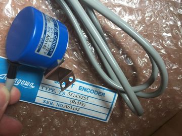
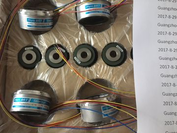
| Brand Name: | Tamagawa |
| Certification: | CE |
| Model Number: | TS5208N23 |
| Minimum Order Quantity: | 1pcs |
|---|---|
| Packaging Details: | carton |
| Delivery Time: | in stock |
| Payment Terms: | T/T, Western Union, MoneyGram |
| Supply Ability: | 100pcs/week |
| TAMAGAWA: | TAMAGAWA | Material: | Iron |
|---|---|---|---|
| Color: | Black | Temperature: | 30-120 |
| Dimension: | 40mm | TS5208N23: | TS5208N23 |
| Japan: | Japan |
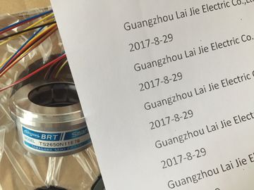
TS5208N23
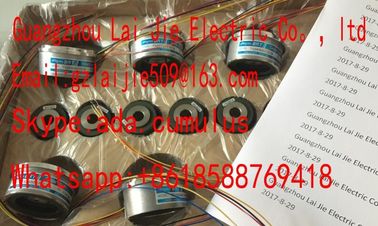
Guang Zhou Lai Jie Electric Co.,LTD
Please contact with “Tommy” for the price
TS252N30E1
AU6270N103E63
TS3653N94E5
TS5208N141E78
TS3630N22E4
TS5146N10
TS5208N500
TS4502N2000E100
TS3503N11E43
TS3653N181E8
TS3684N1E3
TS3631N1E1
TS5146N11
TS5208N510
TS4503N1000E200
TS3062E3
TS3658N3
TS3684N13E8
TS3636N6
TS-5170-N20
TS5208N530
TS4503N1007E200
TS3092N11E12
AU6550N2062
TS3664N1E1
TS3617N1E3
TS3641N1E1
TS5207N530
TS5208N569
TS4503N1022E100
TS3095N2
AU6649N2101
TS3664N1E2
TS3630N1214E3
TS3641N21E6
TS5208N510
TS5208N576
TS4503N1022E200
TS3103N156
FACODER
TS3664N2E3
TS5013N60
TS3641N22E7
TS5208N68
TS5210N450
TS4503N1202E200
TS3103N178
TS3664N2E4
TS5013N61
TS3641N2E3
TS5212N351
TS5210N453
TS4503N1205E200
TS3103N255
TS3664N50
TS5016N60
TS3641N12E3
TS5212N510
TS5210N458
TS4503N1828E100
TS3103N302
OAH14BSD
TS3667N1E2
TS5013N63
TS3641N32
TS5213N550
TS5210N530
TS4503N2000E100
TS3103N40
OAS66
TS3667N11E2
TS5016N61
![]()
![]()
![]()
![]()
| hannel 0 for 4-wire transducer | Figure 6-2 Wiring and block diagram |
| Channel 7 for 2-wire transducer | If you reassign parameters in RUN, the following special characteristic applies. SF LED is lit: |
| Equipotential bonding | If a diagnostics was pending prior to reconfiguration, the SF LEDs (on CPU, IM or module) |
may be lit even though diagnostics are no longer pending and the module is operating
correctly.
Solution:
● Only assign new parameters if no diagnostics is pending, or
● unplug module and plug it in again.
The measurement type and range is configured at the "measuring range" parameter in
STEP 7.
The default setting of the module is "voltage" measurement with "± 10V" range. You can use
these default settings without having to program the SM 331; AI 8 x 16 Bit in STEP 7.
The channels of SM 331; AI 8 x 16 Bit are arranged in four groups of two channels. You can
assign parameters only to one channel group
The table below shows the relevant configuration of channel groups. The channel group
number is required to program SFC parameters in the user program.
Table 6- 7 Assignment of SM 331; AI 8 x 16 Bit channels to channel groups
Set the "disabled" value at the "measuring type" parameter for unused channels. This setting
reduces module cycle times.
As certain programmed inputs may remain unused due to the channel group configuration,
make allowances for the special features of those inputs outlined below in order to be able to
use the diagnostic functions at these used channels:
● Measuring range 1 V to 5 V: wire the used input and unused input of the same channel
group in parallel.
● Current measurement, 4 mA to 20 mA: wire the used input and unused input of the same
channel group in series. Connect a shunt resistor to each programmed and unused
channel.
● Other measuring ranges:Short-circuit the plus and minus inputs of the channel.
The line continuity check is available for the 1 V to 5 V and 4 mA to 20 mA ranges.
Rule for both measuring ranges:
When the line continuity check is enabled, the module logs the wire-break to diagnostics
data when the current drops below 3.6 mA (0.9 V.)The module also triggers a diagnostic interrupt if this function is enabled in the program.A wire break can only be signaled by means of the lit SF LED and the diagnostic bytes mustbe evaluated in the user program if diagnostic interrupts are disabled.When line continuity check is disabled and diagnostic interrupts are enabled, the module
Special features in programming high and low limitsThe programmable limits (hardware interrupt triggers)of SM 331; AI 8 x 16 Bit differ from therange of value shown in the Overview of parameters of SM 331; AI 8 x 16 Bit. table.Reason: The calculation methods deployed in the module software to evaluate the processvariables do not allow the reporting of values up to 32511 in certain situations. The process
value triggering a hardware interrupt at underflow or overflow limits is based on thecalibration factors of the relevant channel, and may vary between the low limits shown in thetable below and the value 32511 (7EFFH).
You may not define any limits which exceed the minimum limits specified in the table below.Table 6- 8 Minimum high and low limits of SM 331; AI 8 x 16 Bit
SM 331; AI 8 x 16 Bit is capable of taking measurements, irrespective of the presence of anyCMV in the AC or DC range.With AC CMV values of a multiple of filter frequency settings, noise is suppressed as a result
of ADC integration time and common mode suppression at the input amplifiers. With AC
CMV < 35 VRMS, the noise suppression of > 100 dB results in negligible measurement errors.