|
| Place of Origin: | Japan |
| Brand Name: | Tamagawa |
| Certification: | CE |
| Model Number: | TS5208N141E78 |
| Minimum Order Quantity: | 1pcs |
|---|---|
| Packaging Details: | carton |
| Delivery Time: | in stock |
| Payment Terms: | T/T, Western Union, MoneyGram |
| Supply Ability: | 100pcs/week |
| TAMAGAWA: | TAMAGAWA | Material: | Iron |
|---|---|---|---|
| Temperature: | 40-120J | Color: | Black |
| Dimension: | 40mm | Wire: | Wire |
| Japan: | Japan | TS5208N141E78: | TS5208N141E78 |
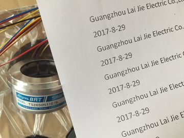
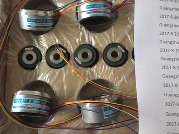
TS5208N141E78
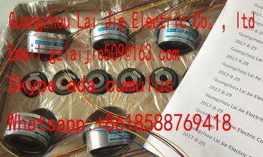
Guang Zhou Lai Jie Electric Co.,LTD
Please contact with “Tommy” for the price
TS3214N44
TS1446N4
TS3684N13E8
TS3664N2E4
TS3624N102E4
TS16N13E12
TS3103N5037
TS4509N1002E200
TS3218
TS1508N202
TS3684N1E3
TS3653N13E7
TS3624N103E5
TS16N18E11
TS3501N
TS4509N1202E200
TS3218N42
TS1508N77
TS3684N2E6
TS3653N12E6
TS3624N203E5
TS2013N191E26
TS3510N39E10
TS4509N1831E200
TS3218N5
TS1508N85
TS3684N3E8
TS3653N2E5
TS3624N22E4
TS2014N181E32
TS3653N95E8
TS4509N2002E200
TS3250E12
TS1526N55
TS3692N103
TS3624N2E3
TS3624N23E5
TS2014N311E32
TS3617N2E7
TS4509N2405E200
TS3275N125
TS1562N102
TS3692N41
TS3653N13E9
TS2014N18E32
TS2014N312E32
TS3617N3E10
TS4509N7000E100
TS3153N15E18
TS1567N132
TS3692N42
TS3653N2E6
TS2014N43E31
TS2018N303E51
TS3617N3E8
TS4514N1021E200
TS3602N213E8
TS3699N112
TS3653N3E7
TS2058N21E1-A
TS20E12
TS3617N13E8
TS4514N1407E200
TS3602N233E8
TS1857N16
TS4603N1532E200
TS2058N21EAA
![]()
![]()
![]()
![]()
| + 5 V from backplane bus | Multiplexer |
| Logic and backplane bus interface | Analog to Digital Converter |
| Electrical isolation |
Current measurement, 2-wire transducer: There are two options of wiring the channel
circuit.
a) Open unused inputs; channel group diagnostics disabled. If you were to enable
diagnostics, the analog module would trigger a single diagnostic interrupt, and light up its
SF LED.
b) Loading the unused input using a 1.5 kΩ to 3.3 kΩ resistor. This allows you to enable
diagnostics for this channel group.
● Current measurement 4 mA to 20 mA, 4-wire transducer: wire the used input and unused
input of the same channel group in series.
Line continuity check for the 4 mA to 20 mA measuring range
If you configured a measuring range of 4 mA to 20 mA, and enabled the line continuity
check, the analog input module logs a wire-break event to diagnostics data when the current
drops below 1.185 mA.
The module also triggers a diagnostics interrupt if this function is enabled in the program.
A wire break can only be signaled by means of the lit SF LED and the diagnostic bytes must
be evaluated in the user program if diagnostics interrupts are disabled.
If you configured a measuring range of 4 mA to 20 mA, disabled the line continuity check,
and enabled diagnostic interrupts, the module triggers a diagnostic interrupt when the
underflow value is reached.
Properties● 8 inputs in 8 channel groups● Programmable resolution for each group (12 bits + sign)
● Measurement type programmable for each channel group:
– Voltage– Current
– Resistance
– Temperature● Any measuring range per channel
● Motor protection / temperature monitoring with PTC in accordance with IEC 60034-11-2type A
● Temperatures recorded via KTY83/110, KTY84/130 silicon temperature sensorsTerminal assignment
The diagrams below show various wiring options. These examples apply to all channels(channel 0 to 7).NoteWhen connecting voltage and current transducers, make sure that the maximum permitted
common-mode voltage CMV of 2 V is not exceeded between the inputs. Prevent measuringerrors byinterconnecting the corresponding M- terminals.4-wire transducer (0/4 mA to 20 mA or ± 20 mA)② 2-wire transducer (4 mA to 20 mA)
③ Equipotential bonding④ Internal supply⑤ + 5 V from backplane bus⑥ Logic and backplane bus interface⑦ Electrical isolation⑧ Multiplexer⑨ Analog to Digital Converter (ADC)⑩ Current source
Figure 6-11 Block diagram and wiring diagram2-wire connection. Insert a bridge between M and S (no lineresistance compensation).
② 3-wire connection