|
| Place of Origin: | Japan |
| Brand Name: | Tamagawa |
| Certification: | CE |
| Model Number: | TS5631N224 |
| Minimum Order Quantity: | 1pcs |
|---|---|
| Packaging Details: | carton |
| Delivery Time: | in stock |
| Payment Terms: | T/T, Western Union, MoneyGram |
| Supply Ability: | 100pcs/week |
| Tamagawa: | Tamagawa | TS5631N224: | TS5631N224 |
|---|---|---|---|
| Japan: | Japan | COLOR: | BLACK |
| Temperature: | 40-120 | Dimension: | 40mm |
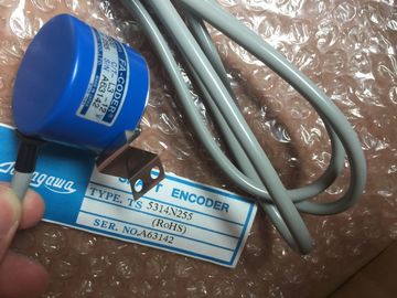
| Wire: | Wire |
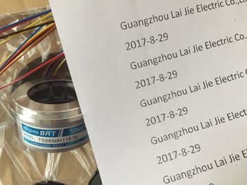
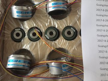
TS5631N224
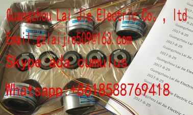
Guang Zhou Lai Jie Electric Co.,LTD
Please contact with “Tommy” for the price
TS4514N1021E200
TS3602N213E8
TS3699N112
TS3653N3E7
TS2058N21E1-A
TS20E12
TS3617N13E8
TS4514N1407E200
TS3602N233E8
TS1857N16
TS4603N1532E200
TS2058N21EAA
TS20N2E11
TS3617N376
TS4514N1828E200
TS3602N31E8
TS-1905N146E6
TS4603N1700E200
TS2087N12E9
TS2142N1E63
TS3617N381
TS4514N2002E200
TS3617N1E1
TS1922N3
TS4603N2002E200
TS2097N1E9
TS2151N1E26
TS3617N3E9
TS4514N2405E200
TS3617N1E2
TS2014N181E32
TS4603N7002E200
TS4602N6321E100
TS3617N2E4
TS3617N13E9
TS4515N1202E200
TS3617N11E1
TS2014N182E32
TS1505N55
TS4515N6000E200
TS4603N1000E100
TS3617N2E5
TS3617N40E3
TS4515N2405E200
TS3617N1E3
TS2014N185E32
TS4602N1000E200
TS4603N1000E200
TS3617N2E6
TS5214N566
TS5205N450
TS5213N551
TS5208N122
TS5208N23
TS5778N171
TS5210N53
TS5320N510
TS5000N632
TS5212N510
TS5213N510
TS5312N616
TS208N101
TS5208N130
TS5213N530
TS5013N68
TS5214N566
TS5200N500
TS5305N616
TS5669N220
TS5214N564
![]()
![]()
![]()
![]()
| the M- terminals may enhance interference immunity. | |
| Current source Figure 6-12 Block diagram and terminal diagram Note |
|
| It is not necessary to interconnect the M- terminals when measuring using resistors, resistance thermometers, PTCs, or silicon temperature sensors. However, interconnection of |
-wire connection. Insert a bridge between M and S (no line resistance compensation).
② 3-wire connection
③ 4-wire connection. The fourth line may not be wired (remains unused)
④ 4-wire connection. The fourth line is routed to the terminal strip in the cabinet but is not wired.
⑤ Internal supply
⑥ + 5 V from backplane bus
⑦ Logic and backplane bus interface
⑧ Electrical isolation
⑨ Multiplexer
⑩ Analog to Digital Converter (ADC)
⑪ Current source
Figure 6-12 Block diagram and terminal diagram
Note
It is not necessary to interconnect the M- terminals when measuring using resistors,
resistance thermometers, PTCs, or silicon temperature sensors. However, interconnection of
the M- terminals may enhance interference immunity.
Interference frequency suppression, error limits
Interference frequency suppression at f = n (f1 ± 1 %), (f1 = interference frequency) n=1.2• Common mode interference (VCM < 2 V)• Seriesmode interference (peak value < rated input range)> 86 dB> 40 dB
Crosstalk between inputs > 50 dB
Operational limit (across entire temperature range, relative to the measurement range end value in theselected inputrange• Volt
Maximum voltage at voltage input U+ (destruction limit) max. 30 V, continuous
Maximum voltage at voltage inputs M+, M-, S- (destruction limit) max. 12 V continuous; 30 V for a duration of max. 1 s
Maximum current at current input I+ (destruction limit) 40 mA
Wiring of the signal transmitters using a 40pin front connector• for voltage measurement• for current measurement– as 2-wire transducer– as 4-wire transducer
supportedsupported, with external supplysupported• for resistance measurementwith 2-wire connectionwith 3-wire connectionwith 4-wireconnectionsupported
supportedsupportedCharacteristics linearization programmable• for resistance thermometers Pt 100 Standard / KlimaNi 100 Standard / KlimaNi 1000 Standard / KlimaLG-Ni 1000 Standard / Klima• Technical unit of temperature measurement Degrees Centigrade, degrees Fahrenheit, Kelvin
You will find a description of the general procedure for assigning parameters to analog
modules in section Programming analog modules (
The spare parts of the SM 331-1KF02 are compatible with the SM 331-1KF01 and are
configured with HSP 2067. HSP 2067 can be installed for STEP7 V5.4, SP5 and higher and
is included for STEP7 V5.4, SP6 and higher.
Unused channels
Set the "disabled" value at the "measurement type" parameter for unused channels. This
setting reduces module cycle times.
Interconnect the M- terminals of unused channels.
Using PTC resistors
PTCs are suitable for monitoring the temperature of or providing thermal protection for
complex drives and transformer windings. The module has no analog values when PTC
resistances are used. Status information on fixed temperature ranges are displyed instead of
analog values.