 |
| Place of Origin: | Japan |
| Brand Name: | Tamagawa |
| Certification: | CE |
| Model Number: | TS2014N181E32 |
| Minimum Order Quantity: | 1pcs |
|---|---|
| Packaging Details: | carton |
| Delivery Time: | in stock |
| Payment Terms: | T/T, Western Union, MoneyGram |
| Supply Ability: | 100pcs/week |
| TAMAGAWA: | TAMAGAWA | TS2014N181E32: | TS2014N181E32 |
|---|---|---|---|
| Material: | Iron | Color: | Black |
| Temperature: | 30-120 | Wire: | Wire |
| Dimension: | 40mm |
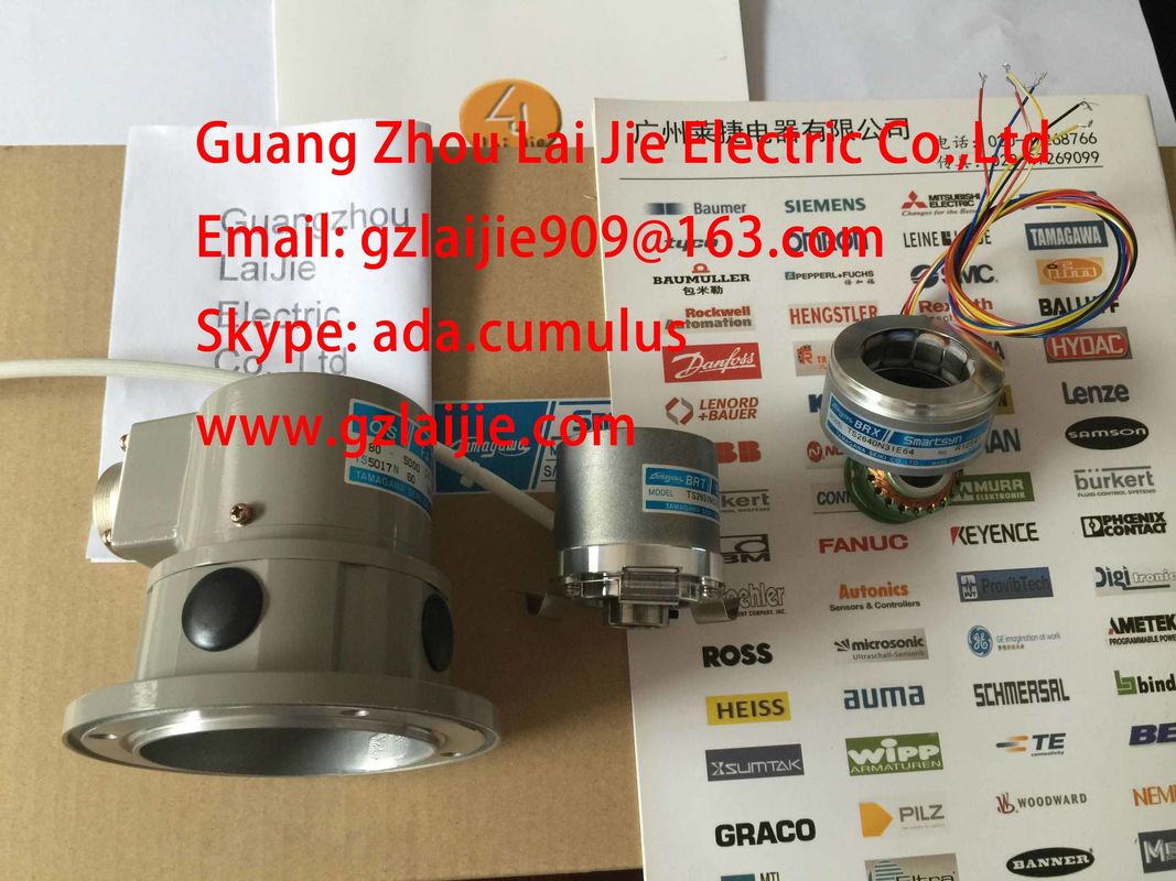
TS2014N181E32
Guang Zhou Lai Jie Electric Co.,LTD
Please contact with “Tommy” for the price
TS5016N60
TS5013N60
TS5208N130
TS5246N160
TS5246N164
TS2650N1E78
TS2650N11E78
TS2650N101E78
TS5212N500
TS5308N616
TS5314N616
TS2640N671E110
TS2605N1E64
TS2640N71E10
TS4503N2000E100
TS4503N2000E200
TS5205N456
TS5205N450
TS5205N454
TS1981N56E19
TS1981N56E18
TS2651N111E78
TS2651N181E78
TS2640N321E64
TS5214N566/N8566
TS5208N8566
TS5667N120
TS5667N420
TS2651N181E78
TS2651N141E78
TS6026N151
TA8481N0300
TA8480N0100
TA8480N0200
TS5000N632
TS2014N181E32
TS2651N131E78
TS5667N420
TS5303N510
TS5246N574
TS5208N143
TS4603N1680E200
TS4603N1680E200
TA8480N0000
TS5216N579AU6802N1
TS5213N510TAMAGAWA
TS3624N22E3
TS5238N352
OIH48-2000P8-L6-5V
TS5212N530
TS5214N8566
TS5214N8566
TS5246N160
TS2620N21E11
TS2650N11E78
TS4602N1033E200
TS5668N41
TS5314N510-2500C/T
35-2000P4-L6-5V
TS5668N43
48-5000p8-L6-5V
TS5217N577
TS3641N
4509N1021E100
OIH48-2500P8-L6-5V60
TS2651N141E78
TS3653N2E5
TS5246N160
TS5246N473
![]()
![]()
![]()
![]()
| The voltage generated at the resistance thermometer is measured across the M+ and Mterminals. | Observe the correct polarity when wiring and connecting the devices |
| and IC - and M- at the resistance thermometer). | |
| The voltage generated at the resistance thermometer is measured across the M+ and Mterminals. |
Supported resistance transducers
● With 4-wire connection
● With 3-wire connection
● With 2-wire connection
The module provides a constant current at terminals IC+ and IC- for current measurements.
The constant current is fed to the resistance for measuring its voltage potential. The constant
current cables must be wired directly to the resistance thermometer/resistor.
Measurements programmed for 4-or 3-wire connections compensate for line resistance and
return considerably higher precision compared to 2-wire connections.
Measurements with programmed 2-wire connections also record line impedance in addition
to their internal resistance.
4-wire connection of a resistance thermometer
Observe the correct polarity when wiring and connecting the devices (IC+ and M+,
and IC - and M- at the resistance thermometer).
Always wire and connect the IC+, M+, IC- and M- lines directly to the resistance
thermometer.
When connecting 3-wire devices to modules equipped with four terminals, you should
generally bridge M- and IC-. Always wire and connect the connected C+ and M+ lines directly
to the resistance thermometer.The image shows the basic wiring. Please observe the notes in the description about therespective module.For 2-wire connections, insert a bridge between the M+ and IC+ and between the M- and ICterminalsof the module. The line impedance is included in the measurement.
This chapter describes the wiring and connecting of thermocouples and corresponding rulesto be observed.The figure below shows several thermocouples and their temperature ranges.Thermocouples consist of a pair of thermal probes and all necessary installation and
connecting parts. The thermocouple pair consists of two wires made of different metals, or of
metal alloys soldered or welded together at their ends.
The different thermocouple types, for example, K, J or N, are derived from different material
compositions. The measuring principle of all thermocouples is the same, irrespective of their
type.