 |
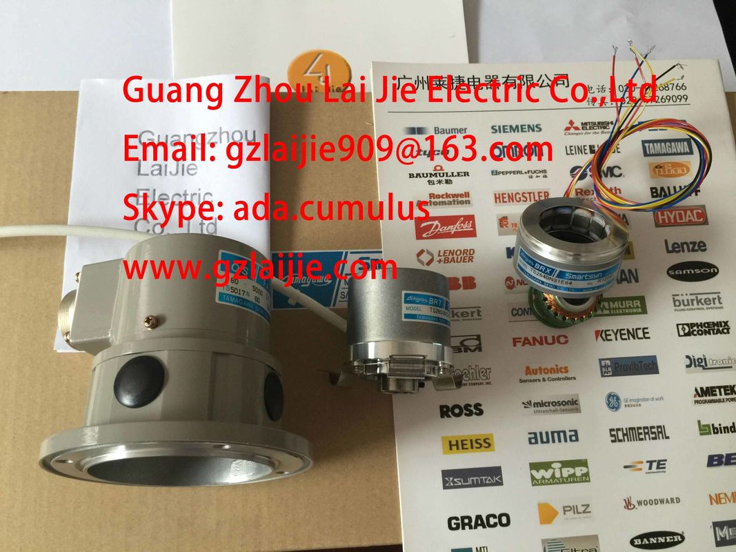
| Place of Origin: | Japan |
| Brand Name: | Tamagawa |
| Certification: | CE |
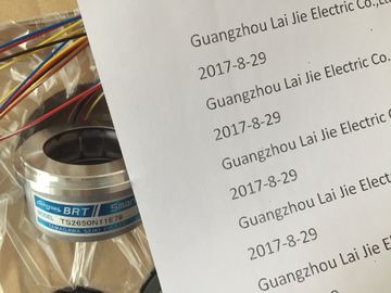
| Model Number: | TS5208N111E78 |
| Minimum Order Quantity: | 1pcs |
|---|---|
| Packaging Details: | carton |
| Delivery Time: | in stock |
| Payment Terms: | T/T, Western Union, MoneyGram |
| Supply Ability: | 100pcs/week |
| Tamagawa: | Tamagawa | TS5208N111E78: | TS5208N111E78 |
|---|---|---|---|
| Japan: | Japan | Material: | Iron |
| Color: | Black | Temperature: | 20-120 |
| Wire: | Wire | Dimension: | 50mm |
TS5208N111E78
Guang Zhou Lai Jie Electric Co.,LTD
Please contact with “Tommy” for the price
TS3630N11E1
TS3664N2E4
TS3653N13E7
TS3653N12E6
TS3653N2E5
TS3624N2E3
TS3653N13E9
TS3653N2E6
TS3653N3E7
TS3653N3E8
TS3653N3E9
TS1980N43E12
TS1980N56E12
TS1981N134E9
TS1981N53E19
TS1981N56E19
TS1981N56E19
TS1982N126E6
TS1982N128E6
TS1982N53E6
TS1982N56E18
TS1983N146E5
TS252N30E1
TS3503N11E43
TS3062E3
TS3092N11E12
TS3095N2
TS3103N156
TS3103N178
TS3103N255
TS3103N302
TS3103N40
TS3132N32
TS3134N21
TS3134N22
TS3134N317
TS3134N52
TS3166
TS3166N43
TS3212N32
TS3214N12
TS3214N13
TS3214N15
TS3214N16
TS3214N44
TS3218
TS3218N42
TS3218N5
TS3250E12
TS3275N125
TS3153N15E18
TS3602N213E8
TS3602N233E8
TS3602N31E8
TS3617N1E1
TS3617N1E2
TS3617N11E1
TS3617N1E3
TS3617N2E4
TS3617N2E5
TS3617N2E6
TS3617N2E7
TS3617N3E10
TS3617N3E8
TS3617N13E8
TS3617N376
TS3617N381
TS3617N3E9
TS3617N13E9
TS3617N40E3
TS3617N47E4
TS3624N1E1
TS3624N21E1
![]()
![]()
![]()
![]()
| At "1" to "0" Max. 2.7 ms (including module cycle time) Load resistor range 48 Ω bis 4kΩ |
|
| Lamp load Max. 5 W Connecting 2 outputs in parallel |
|
| or redundant triggering of a load supported |
To increase performance Not possible
Control of a digital input supportedOperating frequency• with resistive load Max. 100 Hz• With inductive load, to IEC 947-5-1, DC 13 Max. 2 Hz• With lamp load Max. 10 Hz
Limit (internal) of the inductive circuit interruption
voltage to
Typical L+ (-68 V)
Short-circuit of an output Yes, electronic• Response threshold Typical 1.4 A
The load resistances of the actuators must be in the range from 48 Ω to 4 Ω. For larger
values, a suitable resistance must be switched directly on the connection clamps of the
actuator (observe the maximum power loss with signal "1").
The permissible rated voltage of the actuator must be greater than 28.2 V.
The lower response threshold of the actuator must be known in the operating temperaturerange or bedetermined experimentally. The output voltage of the module with signal "0" can
be influenced through parallel switching of a resistance directly on the actuator connection
clamps. With the selection of the resistance, the maximum power loss with signal "1" mustbe observed.● Load resistances between 10 kΩ and 1 MΩ can be reported as short-circuits after L+.● Unwired outputs or loads greater than 1 MΩ are reporeted as "wire-break".3.24.1 Parameters of digital output modulesProgrammingFor general information on programming digital modules, refer to the chapter Programming
digital modules (Page 58).The table below describes the programmable parameters of SM 322; DO 16 x DC 24 V/0.5A, including defaults.Note
A setting of the module through SIMATIC PDM is not possibleTable 3- 23 Setting for the digital output module SM 322; 6ES7322-8BH10-0AB0Parameters Value range Default setting ApplicabilityDiagnostics• Group diagnostics Yes/no no Channel• Load voltage L+ missing Yes/no No Channel group• Discrepancy error Yes/no No Channel group
Diagnostics interrupt yes/no no Module