 |
| Place of Origin: | Japan |
| Brand Name: | Tamagawa |
| Certification: | CE |
| Model Number: | TS5016N60 |
| Minimum Order Quantity: | 1pcs |
|---|---|
| Packaging Details: | carton |
| Delivery Time: | in stock |
| Payment Terms: | T/T, Western Union, MoneyGram |
| Supply Ability: | 100pcs/week |
| Tamagawa: | Tamagawa | TS5016N60: | TS5016N60 |
|---|---|---|---|
| Japan: | Japan | Material: | Iron |
| Temperature: | 30-120 | Color: | Black |
| Dimension: | 40mm |
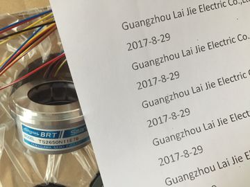
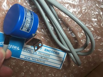
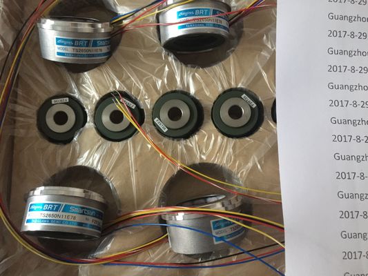
TS5016N60
Guang Zhou Lai Jie Electric Co.,LTD
Please contact with “Tommy” for the price
TS3624N3E5
TS3624N3E6
TS3630N1303E9
TS3630N1309E5
TS3630N1306
TS3630N1E1
TS3630N1E2
TS3630N2E3
TS3630N2E4
TS3630N3E5
TS3630N101E2
TS3630N102E4
TS3630N22E3
TS3630N22E4
TS3631N1E1
TS3636N6
TS3641N1E1
TS3641N21E6
TS3641N22E7
TS3641N2E3
TS3641N12E3
TS3641N32
TS3641N38
TS3643N2
TS3643N212E5
TS3643N233E8
TS3653N11E2
TS3653N12E5
TS3653N13E8
![]()
![]()
![]()
![]()
lectrically isolated
from:
• The backplane
bus interface
electrically isolated
from:
• the CPU
• The load voltage
(not for 2-
DMU)
maximum potential
difference between
inputs (ICM)
50 V DC 60 V DC 11 V DC 2.0 V DC ≤ DC 2.3 V
Special features - - - Motor protection
with PTC and
silicone temperature
sensors
Number of inputs 2 inputs in 1 channel
group
6 inputs in 1 channel
group
8 inputs in 4 channel
groups
8 inputs in 4 channel
groups
8 inputs in 1 channel
group
Resolution programmable for
each channelgroup:• 9 bits+sign
• 12 bits+sign• 14 bits+signProgrammable for
each channelgroup:• 15 bits+signProgrammable foreach channel
group:
• 15 bits+sign
Programmable for
each channel
group:
• 15 bits+sign
programmable for
each channel
group:
15 bits+sign
Measurement type programmable for
each channel
group:
• Voltage
• Current
• Resistance
• Temperature
Programmable for
each channel
group:
• Voltage
• Temperature
programmable for
each channel
group:
• Temperature
programmable for
each channel
group:
• Resistance
• Temperature
Programmable for
each channel
group:• CurrentMeasuring rangeselectionany, per channelgroupany, per channelgroupany, per channel
group
any, per channelgroupany, per channel
groupSupports isochronous
modeYes No Yes Yes Yes
Programmable
diagnosticsNo Yes No No no
Diagnostic interruptprogrammable Programmable Programmable Programmable ProgrammableLimit value monitoring
programmable for1 channelProgrammable for6 channels
programmable for8 channelsprogrammable for8 channelsprogrammable for
8 channelsHardware interruptwhen limit exceededProgrammable Programmable Programmable Programmable programmableHardware interruptat end of cycleno No Programmable Programmable No
Potential ratios electrically isolatedfrom:• the CPU
• The load voltage(not for 2-
DMU)
electrically isolatedfrom:
the CPU
electrically isolated
from:
• of the CPU
electrically isolated
from:
• the CPU
electrically isolated
from:
• the CPU
• The load voltage
(not for 2-
DMU)
maximum potential
difference between
inputs (ICM)
≤ DC 2.3 V 250 V AC - - -
Special features - Calibration - - -
Z sign
2-DMU = 2-wire transducer
* This module is described in the Distributed I/O Device ET 200M HART Analog Modules
manual. You can find the manual on the Internet Number of inputs 4 inputs in 1 channel group 4 inputs in 2 channel groups
Number of outputs 2 outputs in 1 channel group 2 outputs in 1 channel group
Resolution 8 bits 12 bits + sign
Measurement type programmable for each channel group:
• Voltage
• Current
programmable for each channel group:
• Voltage
• Resistance
• Temperature
Output type per channel:
• Voltage
• Current
per channel:
• VoltagePotential ratios • connected to potential of the backplane
bus interface
• electrically isolated to load voltage
electrically isolated to:
• backplane bus interface
• load voltage
Special features Not programmable, measurement and
output type defined by hardwiring
● 8 inputs in 4 channel groups
● Programmable measurement type at each channel group
– Voltage
– Current
● Programmable resolution for each channel group (15 bits + sign)
● Any measuring range per channel group
● Programmable diagnostics and diagnostic interrupt
● Programmable limit value monitoring for 2 channels
Programmable hardware interrupt when limit is exceeded
● High-speed update of measured values
● Electrically isolated to the CPU
● Supports parameter reassignment in RUN
The resolution of measured values is independent of the selected integration time.
Diagnostics
For information on diagnostic messages at the "group diagnostics" parameter, refer to the
table Diagnostic messages of analog input modules.
Hardware interrupts
Hardware interrupts for channel groups 0 and 1 can be programmed in STEP 7. However,
set a hardware interrupt only for the first channel of a channel group, that is, either at
channel 0, or at channel 2
A high-speed update of measured values at two channels of a channel group is three times
compared to the activation of several channel groups.
Example: When channels 0 and 1 are active with 2.5 ms filtering, both channels return new
measured values to the PLC at intervals of 10 ms. (with other settings, the refresh rate is
equivalent to the filter setting.)
High-speed update of measured values is only possible if both channels of channel group 0
and 1 are active, that is, the "measuring type" parameter is set. However, only one of the two
channel groups 0 or 1 may be active (not concurrently active.)
Terminal assignment
The diagrams below show various wiring options
Wire the voltage inputs of the channel voltage in parallel using the corresponding shunt
resistor when measuring current. Bridge the channel input terminals with the adjacent
connector terminals.
Example: You configure channel 0 for current measurement by bridging terminals 22 and 2,
and terminals 23 to 3.
At the channel configured for current measurements, connect the shunt resistor to the
adjacent channel terminals in order to achieve the specified precision
Interference frequency suppression at f = n (f1 1%), (f1 = interference frequency); n= 1, 2, ...
• Common mode interference (CMV < 50 V)
• Series mode interference (peak value of interference < rated
input range)
> 100 dB
> 90 dB
| Crosstalk between inputsBasic error limit | |
| operational limit at 25 °C, relative to measurement range end value in the selected input range | |
| If you reassign parameters in RUN, the following special characteristic applies. SF LED is lit |