 |
| Place of Origin: | Japan |
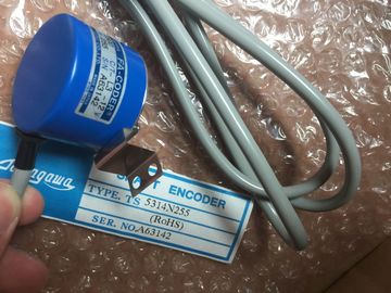
| Brand Name: | Tamagawa |
| Certification: | CE |
| Model Number: | TS5420N60 |
| Minimum Order Quantity: | 1pcs |
|---|---|
| Packaging Details: | carton |
| Delivery Time: | in stock |
| Payment Terms: | T/T, Western Union, MoneyGram |
| Supply Ability: | 100pcs/week |
| TAMAGAWA: | TAMAGAWA | TS5420N60: | TS5420N60 |
|---|---|---|---|
| Color: | Black | Temperature: | 20-90 |
| Dimension: | 80mm | Japan: | Japan |
| Material: | Iron | Wire: | Wire |
TS5420N60
| controllerThe fail-safe modules must be operated with safe functional extra low voltage (SELV, | |
| PELV). You can find more information on safe functional extra-low voltage in the data sheets, fo |
|
| xample, of the applicablSensors and actuators with an external power supply can also be connected to F-modules. Make sure that power is su |
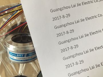
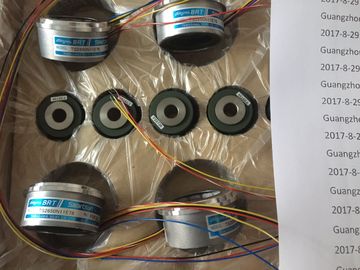
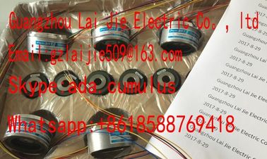
Guang Zhou Lai Jie Electric Co.,LTD
Please contact with “Tommy” for the price
TS5667N420
TS5308N616
TS3462N1E76
TS5214N561
TS5214N510
TS2014N182E32
TS3653N2E5
TS5320N510
TS5016N60
TS5016N60
TS2651N111E78
TS2014N181E32
TS5208N130
TS5214N566
TS5205N450
TS5205N454
TS2651N11E78
TS2651N141E78
TS2651N1E78
TS2651N131E78
TS3103N40
TS3653N2E5
TS3653N3E8
TS3684N1E3
TS3684N2E6
TS3684N3E8
TS3667N3E8
TS3624N2E3
TS3624N2E4
TS3624N3E6
TS3630N1E1
TS3630N2E3
TS3630N1306
TS3630N1303E9
TS3630N1214E3
TS5013N60
TS5013N61
TS5016N60
TS5013N63
TS5013N64
TS5016N61
TS5013N66
TS5016N63
TS5016N64
TS5017N60
TS5019N60
TS5420N60
TS5778N155
supplied to these components from safe functional extra-low
voltage as well. The process signal of Even when a fault occurs, the permissible potential difference between the supply of the
interface module (bus voltage) and the load voltage must not be exceeded.
An external direct electrical connection is on one way to meet this requirement. This also
prevents potential differences from causing voltage additions at the individual voltage
sources, which could cause the fault voltagAlways use power packs or power supply units (24 VDC) with a mains buffering time of at
least 20 ms to ensure adherence to IEC 61131-2.
Also take into consideration the respective requirements of your product stan
ote that instrumentation with sensors and actuators bears a considerable safety
responsibility. Also bear in mind that sensors and actuators generally do not have a service
life of 20 years as defined in IEC 61508:2010 without considerable loss of safety.
The probability of hazardous faults and the rate of hazardous faults of safety functions must
comply with an SIL-defined high limit. A listing of values achieved b high limit. A listing of values achieved by F-modules in the
technical specifications of the F-modules is available under "Fail-safe performance
characteristics"To achieve the respective safety class, suitably qualified sensors and actuators are
necessary.General rule: A single-channel sensor is sufficient to achieve SIL3/Cat.3/PLd. However, to
achieve SIL3/Cat.3/PLd with a single-channel sensor, the sensor itself must be
SIL3/Cat.3/PLd-capable; otherwiIn the case of fail-safe input modules, a "0" value is output to the F-CPU after detection of
faults. You therefore need to make sure that the sensors are implemented in such a way as
to ensure the reliable reaction oExample: In its safety program, an EMERGENCY-STOP sensor must achieve the
shutdown of the respective actuator when it is in the "0" state (EMERGENCY-STOP button
pressed).Observe the following requirements for sensor signals:
• In order to ensure the correct detection of the sensor signals via fail-safe modules with
inputs, you need to make sure that the sensor signals are output The minimum duration of sensor signals for F-modules with inputs depends on the
configured input delay, the parameters of the short circuit test of the sensor supplies, and the
configured discrepancy behavior The duration of the signal must be
greater than the maximum response time of the configured application. Information on
calculating the maximum response time can be found in section "Response times" of the
response time can be found in section "Response times" of the
respective F-module.
The maximum permitted switchingThe fail-safe output modules test the outputs at regular intervals. The F-module briefly
switches off the activated outputs and, if necessary, switches on the deactivated outputs.
You can assign the maximum dm duration of the test pulses (dark and light period) with
parameters.