 |
| Place of Origin: | Japan |
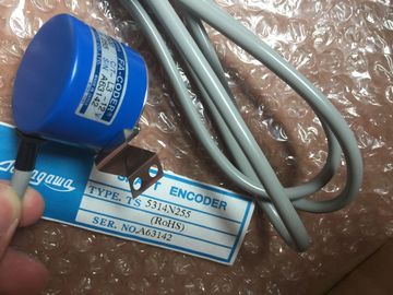
| Brand Name: | Tamagawa |
| Certification: | CE |
| Model Number: | TS5208N131 |
| Minimum Order Quantity: | 1pcs |
|---|---|
| Packaging Details: | carton |
| Delivery Time: | in stock |
| Payment Terms: | T/T, Western Union, MoneyGram |
| Supply Ability: | 100pcs/week |
| TAMAGAWA: | TAMAGAWA | TS5208N131: | TS5208N131 |
|---|---|---|---|
| Japan: | Japan | Color: | Black |
| Temperature: | 20-90 | Wire: | Wire |
| Dimension: | 70mm | Material: | Iron |
TS5208N131
| ossible maximum configuration of a total of 32 modules |
**The PS 60W 24/48/60VDC HF must only be inserted to the left of the CPU. Use a different system |
| which occupy slots 0 to 31. If system power supplies (PS) are needed to the right of the CPU, they each occupy one slot.No connection to the backplane bus. |
for a system power supply (PS) in STEP 7. You do not have to configure a load current supply (PM) in STEP 7. |
| When slot 0 is occupied by a load current supply (PM) in STEP 7, this slot can no longer be used | **The PS 60W 24/48/60VDC HF must only be inserted to the left of the CPU. Use a different system |
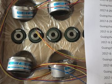
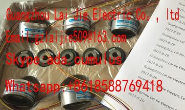
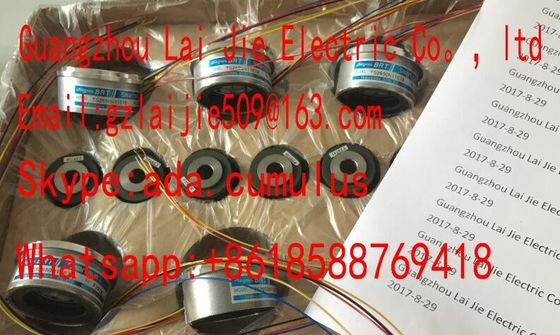
Guang Zhou Lai Jie Electric Co.,LTD
Please contact with “Tommy” for the price
TS5016N63
TS5016N64
TS5017N60
TS5019N60
TS5420N60
TS5778N155
TS5013N68
TS5013N69
TS5208N131
TS5208N23
TS2025N471E69
TS2014N181E32
TS5208N111E78
TS5208N141E78
TS5631N224
PULSE
GENERATOR
RP-182
750PPR
PULSE
GENERATOR
RP-182
1500PPR
PULSE
GENERATORRP-482E,750PPR
ROTALY
ENCODER
RP-112A-T1,750PPR
ROTALY
ENCODER
RP-112A-T1,1500PPR
ROTALY
ENCODER
RP-112A-T1,3000PPR
ROTALY
ENCODER
RP-132,1500PPR
ROTALY
ENCODER
RP-446Z,750PPR
CPU.The integrated system power supply of the interface module feeds 14 W into the
backplane bus. The power budget calculation determines the exact number of I/O
modules that can be operated with the interface module (without optional PS). The
operating principle is described in section Power balance calculation (Page 104).
● Use the integrated power supply for the IM 155-5 PN BA interface module. No 'additional
system power supplies (PS) must be used. You can insert a maximum of 12 modules to
the right of an interface module.
● The following applies for the interface modules IM 155-5 PN ST and IM 155-5 PN HF: A
maximum of three system power supplies (PS) is possible. You can insert one system
power supply (PS) to the left of the interface module and two system power supplies (PS)
to the right of the interface module.
If you insert a system power supply (PS) to the left of the interface module, this yields a
possible maximum configuration of a total of 32 modules (up to 30 modules to the right of
the interface module). If system power supplies (PS) are needed to the right of the
Power supply units for the 24 V DC supply must have a safe galvanic isolation in
accordance with IEC 60364-4-41To protect the automation system/ET 200MP distributed I/O system from
lightning and overvoltages, use overvoltage arresters.
Suitable components for the lightning and overvoltage protection are sAs protection against electric shock you must connect the mounting rail and if necessary, all
other existing protective conductor connections of the automation system /
ET 200MP distributed I/O systeYou may only use conductors in the colors yellow-green for connections to protective
conductor connections.The following describes what you must pay attention to in terms of protection against
electrical influences and/or faults:
● Make sure that the system for discharging electromagnetic interference is connectFor supply, signal and bus lines, you must ensure that the laying of the lines and the
installation is correct.
● For signal and bus lines, you must ensure that a wire/cable breakage or a cross-wire
does not lead to Additional information can be found in the function manual, Designing interference-free