 |
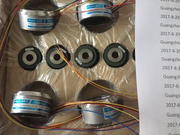
| Place of Origin: | Japan |
| Brand Name: | Tamagawa |
| Certification: | CE |
| Model Number: | TS5214N561 |
| Minimum Order Quantity: | 1pcs |
|---|---|
| Packaging Details: | carton |
| Delivery Time: | in stock |
| Payment Terms: | T/T, Western Union, MoneyGram |
| Supply Ability: | 100pcs/week |
| TAMAGAWA: | TAMAGAWA | TS5214N561: | TS5214N561 |
|---|---|---|---|
| Material: | Iron | Color: | Black |
| Temperature: | 20-90 | Wire: | Wire |
| Dimension: | 80mm | Japan: | Japan |
TS5214N561
| connection modules for connecting sensors and actuators from the field | Engineering with the TIA Portal offers configuration and programming, common data storage and a uniform operating concept for control, visualization and drives. |
| Flexible connection, consisting of front connector with single cores for wiring within the | Integrated Automation (TIA). This tool is the successor of the SIMATIC Selection Tool and combines the known |
| cabinet You can find more information in the SIMATIC TOP connect for - and ET200MP The SIMATIC controllers are integrated into the Totally Integrated Automation Portal. |
he TIA Portal simplifies the integrated engineering in all configuration phases of a plantWith the TIA Selection Tool, you can select, configure and order devices for Totally |
Guang Zhou Lai Jie Electric Co.,LTD
Please contact with “Tommy” for the price
TS3602N31E8
TS3617N1E1
TS3617N1E2
TS3617N11E1
TS3617N1E3
TS3617N2E4
TS3617N2E5
TS3617N2E6
TS3617N2E7
TS3617N3E10
TS3617N3E8
TS3617N13E8
TS3617N376
TS3617N381
TS3617N3E9
TS3617N13E9
TS3617N40E3
TS3617N47E4
TS3624N1E1
TS3624N21E1
TS3624N21E2
TS3624N1E2
TS3624N102E4
TS3624N103E5
TS3624N203E5
TS3624N22E4
TS3624N23E5
TS3624N2E3
TS3624N2E4
TS3624N3E5
TS3624N3E6
TS3630N1303E9
TS3630N1309E5
configurators for automation technology into one tool.
With the TIA Selection Tool, you can generate a complete order list from your product
selection or product configuration.
You can find the TIA Selection Tool on the Internet operation independent of the TIA Portal. The SIMATIC Automation Tool provides you with a
multitude of functions:
● Network browsing and creation of a table showing the accessible devices in the network.
● Flashing of device LEDs or HMI display to locate a deviceDownloading a new program to a CPU or an HMI device
● Downloading from CPU, downloading to CPU or deleting recipe data from a CPU
● Downloading from CPU or deleting data log data from a CPU
● Backup/restore of data from/to a backup file for CPUs and HMI devices
● Downloading service data from a CPU
● Reading the diagnostics buffer of a CPU
● Performing a CPU memory reset
● Resetting devices to factory settings
● Downloading a firmware update to a device the Network Planner, supports
you in planning automation systems and networks based on PROFINET. The tool facilitates
professional and predictive dimensioning of your PROFINET installation as early as in the
planning stage. In addition, SINETPLAN supports you during network optimization and helps
you to exploit network resources optimally and to plan reserves. Thus, you prevent problems
in commissioning or failures during productive operation even in advance of a planned
operation. This increases the availability of the production plant and helps improve
operational safety.
The advantages at a glance
● Network optimization thanks to port-specific calculation of the network load
● Increased production availability thanks to online scan and verification of existing systems
● Transparency before commissioning through importing and simulation of existing STEP 7
projects
● Efficiency through securing existing investment in the long term and optimal exploitation
of resources
3.11.5 PRONETA With PRONETA (PROFINET network analysis), you analyze the plant network
during commissioning. PRONETA features two core functions:
● The topology overview independently scans PROFINET and all connected components.
● The IO check is a fast test of the wiring and the module configuration of a plant.also available to you for free on the Internet.Detect up to 50 networked CPUs via S and establish a connection
● Change CPU operating mode (RUN/STOP)
● Read out CPU diagnostics information and send via e-mail
● Monitor and modify variables and tags
● High security through encrypted communication and encrypted profile data; password to
start app and establish the connectionThe - automation system/ET 200MP distributed I/O system consists of a single-row
configuration in which all modules are installed on one mounting rail. The modules are
connected by means of U connectors, and thus form a self-assembling backplane bus.
You can configure the - automation system/ET 200MP distributed I/O system with
fail-safe and non-fail-safe modules.The integrated system power supply of the CPU supplies 10 W or 12 W (depending on
CPU type) to the backplane bus. The power budget calculation determines the exact
number of modules (without optional PS) that can be operated with the CPU. The
operating principle is described in section Power balance calculation (Page 104).
● A maximum of three system power supplies (PS) is possible. one system power supply
(PS) can be inserted to the left of the CPU and two system power supplies (PS) can be
inserted to the right of the CPU.
● If you insert a system power supply (PS) to the left of the CPU, this yields a