 |
| Place of Origin: | Japan |
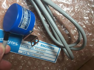
| Brand Name: | Tamagawa |
| Certification: | CE |
| Model Number: | TS5850N60 |
| Minimum Order Quantity: | 1pcs |
|---|---|
| Packaging Details: | carton |
| Delivery Time: | in stock |
| Payment Terms: | T/T, Western Union, MoneyGram |
| Supply Ability: | 100pcs/week |
| TAMAGAWA: | TAMAGAWA | Material: | Iron |
|---|---|---|---|
| Color: | Black | Japan: | Japan |
| Temperature: | 20-90 | Dimension: | 80mm |
| Wire: | Wire | TS5850N60: | TS5850N60 |
TS5850N60
| strips as desired and slide them into the outside of the front cover. The labeling strips are available in the following models: ● Pre-prepared strips that are included with the I/O module as delivered |
You can print labeling strips for the modules in your project with STEP 7. The labeling |
| DIN A4 sheets, pre-perforated strips for machine printing; see section Accessories/spare | strips are exported to Microsoft Word DOCX files and printed from the text editing program. |
| arts (Page 335)Proceed as follows to prepare and install the labeling strips: 1. Label the labeling strip |
You can find more information in the online help. 2. With a pre-perforated strip: Separate the labeling strip from the sheet. |
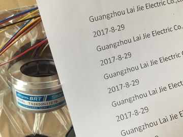
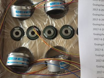
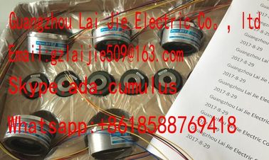
Guang Zhou Lai Jie Electric Co.,LTD
Please contact with “Tommy” for the price
TS1982N53E6
TS1982N56E18
TS1983N146E5
TS252N30E1
TS3503N11E43
TS3062E3
TS3092N11E12
TS3095N2
TS3103N156
TS3103N178
TS3103N255
TS3103N302
TS3103N40
TS3132N32
TS3134N21
TS3134N22
TS3134N317
TS3134N52
TS3166
TS3166N43
TS3212N32
TS3214N12
TS3214N13
TS3214N15
TS3214N16
TS3214N44
TS3218
TS3218N42
TS3218N5
TS3250E12
TS3275N125
TS3153N15E18
TS3602N213E8
TS3602N233E8
TS3602N31E8
TS3617N1E1
TS3617N1E2
TS3617N11E1
TS3617N1E3
TS3617N2E4
lide the labeling strip into the outside of the front cover.On the I/O modules there is free space on the front cover, that permits an additional labeling
or marking on the part of the customer.The front cover provides about 30 mm x 10 mm of space in its lower part for an optional
identifier label.Free space for example for equipment identifiers
Figure 6-21 Optional markingBy configuring the individual hardware components, assigning their parameters, and
connecting them, you communicate to the automation system/ET 200MP
distributed I/O system its preset configuration and operating principle. You perform the work
needed for this in the device and network views in STEP 7.
"Configuring" is understood to mean the arranging, setup and networking of devices and
modules within the device view or network view of STEP 7. STEP 7 graphically represents
modules and racks. Just like "real" module racks, the device view allows the insertion of a
defined number of modules.
When the modules are inserted, STEP 7 automatically assigns the addresses and a unique
hardware identifier (HW identifier). You can change the addresses later. The HW identifiers
cannot be changed.
At startup, the system components compare the configured preset configuration with the
actual configuration of the system. By means of parameter assignment, you can specify the
response of the CPU to errors in the hardware configuration.
"Assigning parameters" is understood to mean setting the properties of the components
used (CPU, modules).
STEP 7 compiles the hardware configuration (the result of "configuring" and "assigning
parameters") and downloads it to the CPU. The CPU then connects to the configured
components and transfers their configuration and parameters. Modules can be replaced very
easily because when a new module is inserted, STEP 7 transfers its configuration and
parameters againWhen a connection exists to a physically present CPU, you can load the configuration of this
CPU (including centrally present modules) from the device into your project using the
"Hardware detection" function. You do not need to manually configure the CPU and the
centrally present modules, as the physical configuration is read out automatically.
If you have already configured a CPU and the centrally present modules and you want to
load the current configuration and parameters in a new project, it is advisable to use the
"Upload device as new station" function. For additional information about this function, refer
to section Backing up and restoring the CPU configuration (Page 244).STEP 7 opens the "Hardware detection for PLC_x" dialog box.
3. In the "Hardware detection for PLC_x" dialog, click "Refresh". Then, select the CPU and
click "DetectSTEP 7 has read out the hardware configuration and the modules and transferred them to
your project. STEP 7 assigns a valid default parameter assignments for all modules. You can
change the parameter assignment subsequentlyIf you want to go online after the hardware detection, you have to first download the detected
configuration to the CPU; otherwise, an error may occur due to inconsistent configurations.
You can find an example of downloading a project to the CPU with STEP 7 in the following
FAQ on the InternetThe properties of the CPUs have special significance for system behavior. For a CPU you
can make the following settings in STEP 7, for example:
● Startup characteristics
● Parameter assignment of the interface(s), for example IP address, subnet mask
● Web server, e.g., activation, user administration, and languages
● OPC UA server