|
| Place of Origin: | Japan |
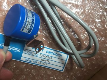
| Brand Name: | Tamagawa |
| Certification: | CE |
| Model Number: | TS5N2E18 |
| Minimum Order Quantity: | 1pcs |
|---|---|
| Packaging Details: | carton |
| Delivery Time: | in stock |
| Payment Terms: | T/T, Western Union, MoneyGram |
| Supply Ability: | 100pcs/week |
| TAMAGAWA: | TAMAGAWA | Material: | Iron |
|---|---|---|---|
| Color: | Black | Temperature: | 20-90 |
| Wire: | Wire | TS5N2E18: | TS5N2E18 |
| Japan: | Japan |
TS5N2E18
| Global Security Certificate Manager ● Cycle times, e.g., maximum cycle time |
Fields that cannot be edited are grayed out. Reference Information about the individual settings can be |
| Protection level for access protection with assigned password parameter ● Time and day settings (daylight saving/standard). For additional information, |
efer to the following FAQ on the Internet The properties that can be set and the corresponding value ranges are specified by STEP 7. |
| Properties for the operation of the display ● System and clock memory |
anual of the respective CPU.In order to address the automation components or modules, they must have unique |
Guang Zhou Lai Jie Electric Co.,LTD
Please contact with “Tommy” for the price
TS1526N55
TS3692N103
TS3624N2E3
TS3624N23E5
TS2014N311E32
TS3617N2E7
TS4509N2405E200
TS3275N125
TS1562N102
TS3692N41
TS3653N13E9
TS2014N18E32
TS2014N312E32
TS3617N3E10
TS4509N7000E100
TS3153N15E18
TS1567N132
TS3692N42
TS3653N2E6
TS2014N43E31
TS2018N303E51
TS3617N3E8
TS4514N1021E200
TS3602N213E8
TS3699N112
TS3653N3E7
TS2058N21E1-A
TS20E12
TS3617N13E8
TS4514N1407E200
TS3602N233E8
TS1857N16
TS4603N1532E200
TS2058N21EAA
TS20N2E11
TS3617N376
TS4514N1828E200
TS3602N31E8
addresses. The following section explains the various address areas.
I/O address
I/O addresses (input/output addresses) are required in the user program to read inputs and
set outputs.
STEP 7 automatically assigns input and output addresses when modules are configured.
Each module uses a continuous range of input and/or output addresses corresponding to its
volume of input and output dataSTEP 7 assigns the address areas of the modules by default to the process image partition 0
("Automatic updating"). This process image partition is updated in the main cycle of the CPU.
Device address (e.g., Ethernet address)
Device addresses are addresses of modules with interfaces to a subnet (e.g., IP address or
PROFIBUS address). They are required to address the various devices on a subnet, for
example, to download a user program.STEP 7 automatically assigns a hardware identifier (HW identifier) for identification and
addressing of modules and submodules. The HW identifier is used, for example, for
diagnostics alarms or for instructions, to identify the faulty module or the addressed module.Figure 7-6 Example of a Hardware identifier from STEP 7
The "System constants" tab contains all hardware identifiers and their symbolic names (of
HW identifier) for the selected module.
The HW identifiers and names of all modules of a device are also available in the default tag
table on the "System constants" tab.The following section describes the addressing of the digital modules. In your user program,
you require the addresses of the channels of the digital module.
Digital module addresses
The address of a digital module's input or output is composed of the byte address and the bit
address. The channels of the digital module are assigned bit addresses.
Example: I 1.2
The example consists of:
I Input -
1 Byte address The byte address depends on the module start address
2 Bit address You read the bit address from the module
When you insert a digital module into a free slot, STEP 7 assigns a default address. You can
change the proposed default address in STEP 7.The following figure shows how the addresses of the individual channels of the digital input
module (e.g., 6ES7521-1BL00-0AB0) are determinedYou can assign symbolic names to the addresses at the following locations in STEP 7:
• PLC tag table
• Properties of the module in the "IO Tags" tabThe value status is additional binary information of a digital input or output signal. It is
entered simultaneously with the process signal in the process image input and provides
information about the validity of the input or output signal.
If you enable the value status for a digital module, then additional bytes are allocated in the
input address area. Each bit in the value status is assigned to a channel and provides
information about the validity of the process value. You can find the assignment in the
product manual for the respective I/O module.
The value status is influenced by all diagnostics that might falsify the process value, e.g. wire
break, short-circuit.
● 1B: A valid process value is being output or read for the channel.
● 0B: A substitute value is being output for the channel, or the channel is