|
| Place of Origin: | Japan |
| Brand Name: | Tamagawa |
| Certification: | CE |
| Model Number: | TS5208N510 |
| Minimum Order Quantity: | 1pcs |
|---|---|
| Packaging Details: | carton |
| Delivery Time: | in stock |
| Payment Terms: | T/T, Western Union, MoneyGram |
| Supply Ability: | 100pcs/week |
| TAMAGAWA: | TAMAGAWA | Material: | Iron |
|---|---|---|---|
| Temperature: | 20-90 | Color: | Gray |
| Wire: | Wire | Dimension: | 80mm |
| Japan: | Japan | TS5208N510: | TS5208N510 |
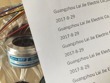
TS5208N510
| Surge immunity | For DC systems (I/O signals, DC power systems) external protection is required. EN 61000-4- |
| AC systems - 2 kV common mode, 1kV differential mode | Conducted disturbances 150 kHz to 80 MHz, 10 V RMS, 80% AM at 1kHz EN 61000-4-11 Voltage dips AC systems |
| DC systems - 2 kV common mode, 1kV differential mode | 0% for 1 cycle, 40% for 12 cycles and 70% for 30 cycles at 60 Hz For systems that must start up in the range of -20° C to 0° C, the user program should |
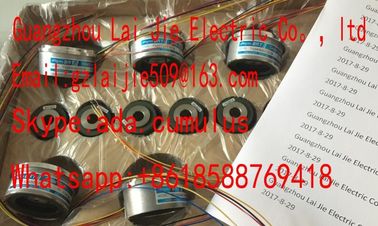
Guang Zhou Lai Jie Electric Co.,LTD
Please contact with “Tommy” for the price
TS2650N11E78
TS4507N2000E100
TS3214N12
RFH1024-22-1M-68
TS3682N1
TS3617N1E1
TS3624N1E1
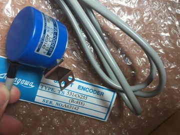
TS1508N255
TS2651N111E78
TS4507N2070E100
TS3214N13
RFH102422IM
TS3682N2
TS3617N1E2
TS3624N21E1
TS1508N257
TS26541N131E78
TS4507N2405E200
TS3214N15
TA8110N2121E802
TS3684N11E3
TS3617N2E4
TS3624N21E2
TS1508N260
delay energizing outputs for 10 seconds following startupIP20 Mechanical Protection, EN 60529
● Protects against finger contact with high voltage as tested by standard probe. External
protection required for dust, dirt, water and foreign objects of < 12.5mm in diameter.When a mechanical contact turns on output power to the S7-1200 CPU, or any digital
signal module, it sends a "1" signal to the digital outputs for approximately 50
microseconds. This could cause unexpected machine or process operation which could
result in death or serious injury to personnel and/or damage to equipment. You must plan
for this, especially if you are using devices which respond to short duration pulses. Reverse voltage protection circuitry is provided on each terminal pair of +24 VDC power or
user input power for CPUs, signal modules (SMs), and signal boards (SBs). It is still possible
to damage the system by wiring different terminal pairs in opposite polarities.
Some of the 24 VDC power input ports in the S7-1200 system are interconnected, with a
common logic circuit connecting multiple M terminals. For example, the following circuits are
interconnected when designated as "not isolated" in the data sheets: the 24 VDC power
supply of the CPU, the power input for the relay coil of an SM, or the power supply for a nonisolated
analog input. All non-isolated M terminals must connect to the same external
reference potential. Connecting non-isolated M terminals to different reference potentials will cause unintended
current flows that may cause damage or unpredictable operation in the PLC and any
connected equipment.
Failure to comply with these guidelines could cause damage or unpredictable operation
which could result in death or serve personal injury and/or property damage.
Always ensure that all non-isolated M terminals in an S7-1200 system are connected to the
same reference potential. Connecting non-isolated M terminals to different reference potentials will cause unintended
current flows that may cause damage or unpredictable operation in the PLC and any
connected equipment.
Failure to comply with these guidelines could cause damage or unpredictable operation
which could result in death or serve personal injury and/or property damage.
Always ensure that all non-isolated M terminals in an S7-1200 system are connected to the
same reference potential. The CPU provides dedicated HMI connections to support up to 3 HMI devices. (You can have up to 2 SIMATIC Comfort
panels.) The total number of HMI is affected by the types of HMI panels in your configuration. For example, you could
have up to three SIMATIC Basic panels connected to your CPU, or you could have up to two SIMATIC Comfort panels
with one additional Basic panel. For CPU models with relay outputs, you must install a digital signal board (SB) to use the pulse outputs.
2 Depending on your pulse receiver and cable, an additional load resistor (at least 10% of rated current) may improve
pulse signal quality and noise immunity. The CPU provides dedicated HMI connections to support up to 3 HMI devices. (You can have up to 2 SIMATIC Comfort
panels.) The total number of HMI is affected by the types of HMI panels in your configuration. For example, you could
have up to three SIMATIC Basic panels connected to your CPU, or you could have up to two SIMATIC Comfort panels
with one additional Basic panel. 16 Kbytes for startup and program cycle (including associated FBs and FCs)
4 Kbytes for standard interrupt events including FBs and FCs
4 Kbytes for error interrupt events including FBs and FCs