|
| Place of Origin: | Japan |
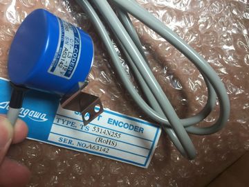
| Brand Name: | Tamagawa |
| Certification: | CE |
| Model Number: | TS5212N510 |
| Minimum Order Quantity: | 1pcs |
|---|---|
| Packaging Details: | carton |
| Delivery Time: | in stock |
| Supply Ability: | 100pcs/week |
| TAMAGAWA: | TAMAGAWA | Material: | Iron |
|---|---|---|---|
| Color: | Black | Japan: | Japan |
| TS5212N510: | TS5212N510 | Temperature: | 20-90 |
| Dimension: | 80mm | Wire: | Wire |
TS5212N510
| Quadrature phase: 80 KHz (Ia.0 to Ia.5) and 20 KHz (Ia.6 to Ib.5) | 24 VDC Sensor Power Out |
| Number of inputs on simultaneously 7 (no adjacent points) at 60° C horizontal or 50° C vertical | For additional noise immunity, connect "M" to chassis ground even if not using sensor supply. ② For si |
| 14 at 55° C horizontal or 45° C vertical Cable length (meters) 500 m shielded, 300 m unshielded |
For sourcing inputs, connect "+" to "M". |
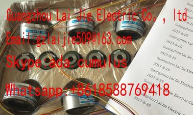
Guang Zhou Lai Jie Electric Co.,LTD
Please contact with “Tommy” for the price
TS5170
TS5410
TS5200N500
TS5146
TS5270
TS5610
TS5620
TS1857
TS5607
TS5668N20
TS5667N120
TS5667N420
TS5645
TS5647
TS5648
TS5643
TS2223
TS2224
TS2225
TS20E12
TS13E11
TS5308N616
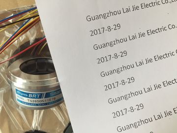
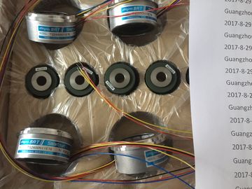
TS2650N11E78
TS5420N60
TS5208N131
TS3462N1E76
48-2500P8-L6-5VC/T-L3-12V
TS-5016N-60
TS5214N561
TS5214N510
TS2014N182E32
TS3653N2E5
TS5320N510
TS5016N-60
TS5016N60
TS5305N616
Note: X11 connectors must be gold. See Appendix C, Spare Parts for order number. 24 VDC Sensor Power Out
For additional noise immunity, connect "M" to chassis ground even if not using sensor
supply.
② For sinking inputs, connect "-" to "M" (shown). For sourcing inputs, connect "+" to "M".
Note: X11 connectors must be gold. See Appendix C, Spare Parts for order numbe① 24 VDC Sensor Power Out
For additional noise immunity, connect "M" to chassis ground even if not using sensor
supply.
② For sinking inputs, connect "-" to "M" (shown). For sourcing inputs, connect "+" to "M".
Note: X11 connectors must be gold. See Appendix C, Spare Parts for order number For SM 1231 AI 4 x 13 bit: If a voltage greater than +30 VDC or less than -15 VDC is applied to the input, the resulting
value will be unknown and the corresponding overflow or underflow may not be active. Unused analog inputs should be shorted.
When the inputs are configured for "current" mode, no current will flow through the input
unless you supply external power to the module. Voltage or Current (differential): Selectable in groups of 2
Range ±10 V, ±5 V, ±2.5 V, or 0 to 20 mA
Full scale range (data word) -27,648 to 27,648
Overshoot/undershoot range
(data word)
Voltage: 32,511 to 27,649 / -27,649 to -32,512
Current: 32,511 to 27,649 / 0 to -4864
Refer to the section on input ranges for voltage and current (Page 770).
Overflow/underflow (data word) Voltage: 32,767 to 32,512 / -32,513 to -32,768
Current: 32,767 to 32,512 / -4865 to -32,768
Refer to the section on input ranges for voltage and current (Page 770).
Resolution 12 bits + sign bit
Maximum withstand voltage/current ±35 V / ±40 mA
Smoothing None, weak, medium, or strong
Refer to the section on step response times (Page 769).
Noise rejection 400, 60, 50, or 10 Hz
Refer to the section on sample rates (Page 769).The overflow, underflow and low voltage diagnostic alarm information will be reported in the analog data values even if
the alarms are disabled in the module configuration.
2 When wire break alarm is disabled and an open wire condition exists in the sensor wiring, the module may report
random values.
The SM 1231 Thermocouple (TC) analog signal module measures the value of voltage
connected to the module inputs. The temperature measurement type can be either
"Thermocouple" or "Voltage".
● "Thermocouple": The value will be reported in degrees multiplied by ten (for example, 25.3
degrees will be reported as decimal 253).
● "Voltage": The nominal range full scale value will be decimal 27648. Thermocouples are formed whenever two dissimilar metals are electrically bonded to each
other. A voltage is generated that is proportional to the junction temperature. This voltage is
small; one microvolt could represent many degrees. Measuring the voltage from a
thermocouple, compensating for extra junctions, and then linearizing the result forms the
basis of temperature measurement using thermocouples.
When you connect a thermocouple to the SM 1231 Thermocouple module, the two dissimilar
metal wires are attached to the module at the module signal connector. The place where the
two dissimilar wires are attached to each other forms the sensor thermocouple.
Two more thermocouples are formed where the two dissimilar wires are attached to the
signal connector. The connector temperature causes a voltage that adds to the voltage from
the sensor thermocouple. If this voltage is not corrected, then the temperature reported will
deviate from the sensor temperature.
Cold junction compensation is used to compensate for the connector thermocouple.
Thermocouple tables are based on a reference junction temperature, usually zero degrees
Celsius. The cold junction compensation compensates the connector to zero degrees
Celsius. The cold junction compensation restores the voltage added by the connector
thermocouples. The temperature of the module is measured internally, then converted to a
value to be added to the sensor conversion. The corrected sensor conversion is then
linearized using the thermocouple tables.
For optimum operation of the cold junction compensation, the thermocouple module must be
located in a thermally stable environment. Slow variation (less than 0.1° C/minute) in
ambient module temperature is correctly compensated within the module specifications. Air
movement across the module will also cause cold junction compensation errors.
If better cold junction error compensation is needed, an external iso-thermal terminal block