|
| Place of Origin: | Japan |
| Brand Name: | Tamagawa |
| Certification: | CE |
| Model Number: | TS5013N63 |
| Minimum Order Quantity: | 1pcs |
|---|---|
| Packaging Details: | carton |
| Delivery Time: | in stock |
| Payment Terms: | T/T, Western Union, , MoneyGram |
| Supply Ability: | 100pcs/week |
| TAMAGAWA: | TAMAGAWA | Material: | Iron |
|---|---|---|---|
| Color: | Black | Japan: | Japan |
| Wire: | Wire | Temperature: | 20-90 |
| Dimension: | 80mm | TS5013N63: | TS5013N63 |
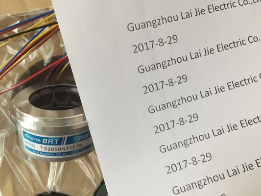
TS5013N63
| he RTD module needs to have the current loop continuous to eliminate extra stabilization time which is automatically added to an unused channel that is not deactivated. |
hen 500 Ω and 1000 Ω RTD ranges are used with other lower value resistors, the error may increase to two times the specified error. |
| For consistency the RTD module should have a resistor connected (like the 2-wire RTD connection)The module reports 32767 on any activated channel with no sensor connected. If open wire |
Best accuracy will be achieved for the 10 Ω RTD ranges if 4 wire connections are used. The resistance of the connection wires in 2 wire mode will cause an error in the sensor |
| detection is also enabled, the module flashes the appropriate red LEDs. | reading and therefore accuracy is not guaranteedAfter power is applied, the module performs internal calibration for the analog-to-digital |
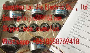
Guang Zhou Lai Jie Electric Co.,LTD
Please contact with “Tommy” for the price
TS3636N6
TS-5170-N20
TS5208N530
TS4503N1007E200
TS3092N11E12
AU6550N2062
TS3664N1E1
TS3617N1E3
TS3641N1E1
TS5207N530
TS5208N569
TS4503N1022E100
TS3095N2
AU6649N2101
TS3664N1E2
TS3630N1214E3
TS3641N21E6
TS5208N510
TS5208N576
TS4503N1022E200
TS3103N156
FACODER
TS3664N2E3
TS5013N60
TS3641N22E7
TS5208N68
TS5210N450
TS4503N1202E200
TS3103N178
TS3664N2E4
TS5013N61
TS3641N2E3
TS5212N351
TS5210N453
TS4503N1205E200
TS3103N255
TS3664N50
TS5016N60
TS3641N12E3
converter. During this time the module reports a value of 32767 on each channel until valid
data is available on that channel. Your user program may need to allow for this initialization
time. Because the configuration of the module can vary the length of the initialization time,
you should verify the behavior or the module in your configuration. If required, you can
include logic in your user program to accommodate the initialization time of the moduleTo maintain module resolution and accuracy when the 400 Hz filter is selected, the integration time is 10 ms. This
selection also rejects 100 Hz and 200 Hz noiseWhen switching frequencies above 20 kHz, it is important that the digital inputs receive a
square wave. Consider the following options to improve the signal quality to the inputs:
Minimize the cable length
Change a driver from a sink only driver to a sinking and sourcing driver
Change to a higher quality cable
Reduce the circuit/components from 24 V to 5 V
Add an external load at the input Because both sinking and sourcing configurations are supported by the same circuitry, the active state of a sourcing
load is opposite that of a sinking load. A source output exhibits positive logic (Q bit and LED are ON when the load has
current flow), while a sink output exhibits negative logic (Q bit and LED are OFF when the load has current flow). If the
module is plugged in with no user program, the default for this module is 0 V, which means that a sinking load will be
turned ON. Because both sinking and sourcing configurations are supported by the same circuitry, the active state of a sourcing
load is opposite that of a sinking load. A source output exhibits positive logic (Q bit and LED are ON when the load has
current flow), while a sink output exhibits negative logic (Q bit and LED are OFF when the load has current flow). If the
module is plugged in with no user program, the default for this module is 0 V, which means that a sinking load will be
turned ON. When switching frequencies above 20 kHz, it is important that the digital inputs receive a
square wave. Consider the following options to improve the signal quality to the inputs:
Minimize the cable length
Change a driver from a sink only driver to a sinking and sourcing driver
Change to a higher quality cable
Reduce the circuit/components from 24 V to 5 V