|
| Place of Origin: | Japan |
| Brand Name: | Tamagawa |
| Certification: | CE |
| Model Number: | TS5210N530 |
| Minimum Order Quantity: | 1pcs |
|---|---|
| Packaging Details: | carton |
| Delivery Time: | in stock |
| Payment Terms: | T/T, Western Union, MoneyGram |
| Supply Ability: | 100pcs/week |
| TAMAGAWA: | TAMAGAWA | Material: | Iron |
|---|---|---|---|
| Color: | Black | Japan: | Japan |
| TS5210N530: | TS5210N530 | Temperature: | 20-90 |
| Dimension: | 70mm | Wire: | Wire |
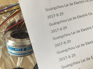
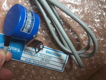
TS5210N530
| 25.3 degrees will be reported as decimal 253). | other. A voltage is generated that is proportional to the junction temperature. This voltage |
| "Voltage": The nominal range full scale value will be decimal 27648. | is small; one microvolt could represent many degrees. Measuring the voltage from athermocouple, compensating for extra junctions, |
| hermocouples are formed whenever two dissimilar metals are electrically bonded to each | thermocouple, compensating for extra junctions, |
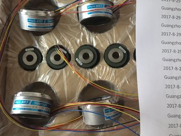
Guang Zhou Lai Jie Electric Co.,LTD
Please contact with “Tommy” for the price
TS3653N12E5
TS5320N632
TS2640N141E172
TS4507N1202E200
OSE5KN-6-12-108
TS3674N37
TS5013N69
TS3653N13E8
TS5420
TS2640N181E100
TS4507N1205E200
TS3166N43
TS3679N2E1
TS5208N131
TS3653N1E1
TS5641N150
TS2640N321E64
TS4507N1229E200
TS3212N32
RFH102422
TS3679N3E1
TS5208N111E78
TS3617N47E4
TS1508N211
TS2650N11E78
TS4507N2000E100
TS3214N12
RFH1024-22-1M-68
TS3682N1
TS3617N1E1
TS3624N1E1
TS1508N255
TS2651N111E78
TS4507N2070E100
TS3214N13
RFH102422IM
TS3682N2
TS3617N1E2
and then linearizing the result forms the
basis of temperature measurement using thermocouples.
When you connect a thermocouple to the SM 1231 Thermocouple module, the two dissimilar
metal wires are attached to the module at the module signal connector. The place where the
two dissimilar wires are attached to each other forms the sensor thermocouple.
Two more thermocouples are formed where the two dissimilar wires are attached to the
signal connector. The connector temperature causes a voltage that adds to the voltage from
the sensor thermocouple. If this voltage is not corrected, then the temperature reported will
deviate from the sensor temperature.
Cold junction compensation is used to compensate for the connector thermocouple.
Thermocouple tables are based on a reference junction temperature, usually zero degrees
Celsius. The cold junction compensation compensates the connector to zero degrees
Celsius. The cold junction compensation restores the voltage added by the connector
thermocouples. The temperature of the module is measured internally, then converted to a
value to be added to the sensor conversion. The corrected sensor conversion is then
linearized using the thermocouple tables.
For optimum operation of the cold junction compensation, the thermocouple module must be
located in a thermally stable environment. Slow variation (less than 0.1° C/minute) in
ambient module temperature is correctly compensated within the module specifications. Air
movement across the module will also cause cold junction compensation errors.
If better cold junction error compensation is needed, an external iso-thermal terminal block
may be used. The thermocouple module provides for use of a 0° C referenced or 50° C
referenced terminal blockThe ranges and accuracy for the different thermocouple types supported by the SB 1231
Thermocouple signal board are shown in the table below.
Table A- 197 SB 1231 Thermocouple selection tableThermocouple values below the under-range minimum value are reported as -32768.
2 Thermocouple values above the over-range minimum value are reported as 32767.
3 Internal cold junction error is ±1.5°C for all ranges. This adds to the error in this table. The signal board requires at least
30 minutes of warmup time to meet this specification.
Table A- 198 Filter selection table for the SB 1231 Thermocouple To maintain module resolution and accuracy when 400 Hz rejection is selected, the integration time is 10 ms. This
selection also rejects 100 Hz and 200 Hz noise.
It is recommended for measuring thermocouples that a 100 ms integration time be used. The
use of smaller integration times will increase the repeatability error of the temperature
readings.
Note
After power is applied to the module, it performs internal calibration for the analog to digital
converter. During this time, the module reports a value of 32767 on each channel until valid
data is available on that channel. Your user program may need to allow for this initialization
time. The overflow and underflow diagnostic alarm information will be reported in the analog data values even if the alarms
are disabled in the module configuration.
2 For resistance ranges underflow detection is never enabled.
3 When wire break alarm is disabled and an open wire condition exists in the sensor wiring, the module may report
random values.
The SM 1231 RTD analog signal board measures the value of resistance connected to the
signal board inputs. The measurement type can be selected as either "Resistor" or "Thermal
resistor".
● "Resistor": The nominal range full scale value will be decimal 27648.
● "Thermal resistor": The value will be reported in degrees multiplied by ten (for example,
25.3 degrees will be reported as decimal 253).
The SB 1231 RTD signal board supports measurements with 2-wire, 3-wire and 4-wire
connections to the sensor resistor.
Table A- 204 Wiring diagram for SB 1231 AI 1 x 16 bit RTD The module reports 32767 on any activated channel with no sensor connected. If open wire
detection is also enabled, the module flashes the appropriate red LEDs.
When 500 Ω and 1000 Ω RTD ranges are used with other lower value resistors, the error
may increase to two times the specified error.
Best accuracy will be achieved for the 10 Ω RTD ranges if 4 wire connections are used.
The resistance of the connection wires in 2 wire mode will cause an error in the sensor
reading and therefore accuracy is not guaranteed. After power is applied, the module performs internal calibration for the analog-to-digital
converter. During this time the module reports a value of 32767 on each channel until valid
data is available on that channel. Your user program may need to allow for this initialization
time. Because the configuration of the module can vary the length of the initialization time,
you should verify the behavior or the module in your configuration. If required, you can
include logic in your user program to accommodate the initialization time of the moduley Board
The S7-1200 BB 1297 Battery Board is designed for long-term backup of the Real-time
clock. It is pluggable in the signal board slot of the S7-1200 CPU (firmware 3.0 and later
versions). You must add the BB 1297 to the device configuration and download the
hardware configuration to the CPU for the BB to be functional.
The battery (type CR1025) is not included with the BB 1297 and must be purchased by the
user.
Note
The BB 1297 is mechanically designed to fit the CPUs with the firmware 3.0 and later
versions.
Do not use the BB 1297 with earlier version CPUs as the BB 1297 connector will not plug
into the CPU. Order number 6GK7 242-5DX30-0XE0
Interfaces
Connection to PROFIBUS 9-pin D-sub female connector