 |
| Place of Origin: | Japan |
| Brand Name: | Tamagawa |
| Certification: | CE |
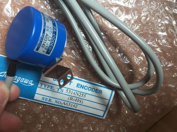
| Model Number: | TS5205N450 |
| Minimum Order Quantity: | 1pcs |
|---|---|
| Packaging Details: | carton |
| Delivery Time: | in stock |
| Payment Terms: | T/T, Western Union, MoneyGram |
| Supply Ability: | 100pcs/week |
| TAMAGAWA: | TAMAGAWA | Material: | Iron |
|---|---|---|---|
| TS5205N450: | TS5205N450 | Color: | Black |
| Japan: | Japan | Temperature: | 30-90 |
| Wire: | Wire |
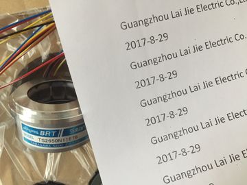
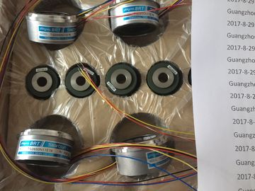
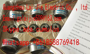
TS5205N450
| The following table shows the HSC input assignments for both the on-board I/O of the CPU 1211C and an SB |
(Reset is available only for "Counting" mode.) ● For two-phase: CU is the Clock Up input, |
| (If the SB has only 2 inputs, only 4.0 and 4.1 inputs are available.) ● For single-phase: |
D is the Clock Down input, and [R] is an optional external reset input. |
| C is the Clock input, [d] is the optional direction input, and [R] is an optional external reset input. |
(Reset is available only for "Counting" mode.) ● For AB-phase quadrature: |
Please contact with “Tommy” for the price
TS3624N21E1
TS1508N257
TS26541N131E78
TS4507N2405E200
TS3214N15
TA8110N2121E802
TS3684N11E3
TS3617N2E4
TS3624N21E2
TS1508N260
TS3033N4E2
TS4507N6205E200
TS3214N16
TA8110N2121E916
TS3684N12E6
TS3630N11E1
TS3624N1E2
TS1613N200
TS3063N15E8
TS4507N8029E200
TS3214N44
TS1446N4
TS3684N13E8
TS3664N2E4
TS3624N102E4
TS16N13E12
TS3103N5037
TS4509N1002E200
TS3218
TS1508N202
TS3684N1E3
TS3653N13E7
TS3624N103E5
A is the Clock A input, B is the Clock B input, and [R] is an
optional external reset input. (Reset is available only for "Counting" mode.)
Table 9- 6 HSC input assignments for CPU 1211C HSC 1 and HSC 2 can be configured for either the on-board inputs or for an SB.
2 HSC 5 and HSC 6 are available only with an SB. HSC 6 is available only with a 4-input SB.
3 An SB with only 2 digital inputs provides only the 4.0 and 4.1 inputs.
The following table shows the HSC input assignments for both the on-board I/O of the CPU
1212C and an SB. (If the SB has only 2 inputs, only 4.0 and 4.1 inputs are available.)
● For single-phase: C is the Clock input, [d] is the optional direction input, and [R] is an
optional external reset input. (Reset is available only for "Counting" mode.)
● For two-phase: CU is the Clock Up input, CD is the Clock Down input, and [R] is an
optional external reset input. (Reset is available only for "Counting" mode.)
● For AB-phase quadrature: A is the Clock A input, B is the Clock B input, and [R] is an
optional external reset input. (Reset is available only for "Counting" mode.) 1 HSC 1 and HSC 2 can be configured for either the on-board inputs or for an SB.
2 HSC 5 and HSC 6 are available only with an SB. HSC 6 is available only with a 4-input SB.
3 An SB with only 2 digital inputs provides only the 4.0 and 4.1 inputs.For CPU 1214C: HSC 1, HSC 2, HSC 5 and HSC 6 can be configured for either the on-board
inputs or for an SB.
2 An SB with only 2 digital inputs provides only the 4.0 and 4.1 inputs.
Accessing the current value for the HSC
Note
When you enable a pulse generator for use as a PTO, a corresponding HSC is assigned to
this PTO. HSC1 is assigned for PTO1, and HSC2 is assigned for PTO2. The assigned HSC
belongs completely to the PTO channel, and the ordinary output of the HSC is disabled. The
HSC value is only used for the internal functionality. You cannot monitor the current value
(for example, in ID1000) when pulses are occurring.
The CPU stores the current value of each HSC in an input (I) address. The following table
shows the default addresses assigned to the current value for each HSC. You can change
the I address for the current value by modifying the properties of the CPU in the Device
Configuration.
Table 9- 10 Current value of the HSC The CPU allows you to configure up to 6 high-speed
counters. You edit the "Properties" of the CPU to
configure the parameters of each individual HSC.
Use the CTRL_HSC instruction in your user program to
control the operation of the HSC.
Enable the specific HSC by selecting the "Enable" option
for that HSC. When you enable the high speed counter and select input points for it, the input filter settings
for these points are configured to 800 ns. Each input point has a single filter configuration
that applies to all uses: process inputs, interrupts, pulse catch, and HSC inputs.
WARNING
If the filter time for a digital input channel is changed from a previous setting, a new "0"
level input value may need to be presented for up to 20.0 ms accumulated duration before
the filter becomes fully responsive to new inputs. During this time, short "0" pulse events of
duration less than 20.0 ms may not be detected or counted.
This changing of filter times can result in unexpected machine or process operation, which
may cause death or serious injury to personnel, and/or damage to equipment.
To ensure that a new filter time goes immediately into effect, a power cycle of the CPU
must be applied.After enabling the HSC, configure the other parameters, such as counter function, initial
values, reset options and interrupt events. STEP 7 provides the following PID instructions for the CPU:
● The PID_Compact instruction is used to control technical processes with continuous
input- and output variables.