 |
| Place of Origin: | Japan |
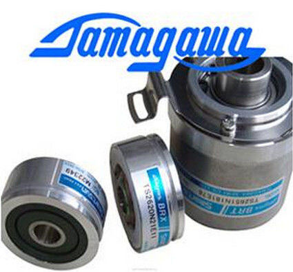
| Brand Name: | Tamagawa |
| Certification: | CE |
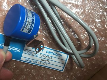
| Model Number: | TS5213N551 |
| Minimum Order Quantity: | 1pcs |
|---|---|
| Packaging Details: | carton |
| Delivery Time: | in stock |
| Payment Terms: | T/T, Western Union, MoneyGram |
| Supply Ability: | 100pcs/week |
| TAMAGAWA: | TAMAGAWA | Material: | Iron |
|---|---|---|---|
| Color: | Black | Temperature: | 30-90 |
| Dimension: | 70mm | Wire: | Wire |
| Japan: | Japan | TS5213N551: | TS5213N551 |
TS5213N551
| not calculate the output value in every cycle. Do not execute the PID instruction in the main program cycle OB (such as OB 1). |
All other functions of PID instruction are executed at every call. The PID (Proportional/Integral/Derivative) controller measures the time interval between two calls and then evaluates the results for monitoring the sampling time. |
| The sampling time of the PID algorithm represents the time between two calculations of the output value (control value). |
A mean value of the sampling time is generated at each mode changeover and during initial startup. |
| The output value is calculated during self-tuning and rounded to a multiple of the cycle time. |
This value is used as reference for the monitoring function and is used for calculation. |
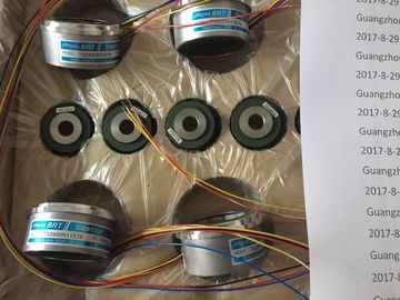
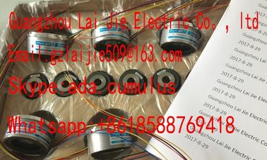
Guang Zhou Lai Jie Electric Co.,LTD
Please contact with “Tommy” for the price
TS3218
TS1508N202
TS3684N1E3
TS3653N13E7
TS3624N103E5
TS16N18E11
TS3501N
TS4509N1202E200
TS3218N42
TS1508N77
TS3684N2E6
TS3653N12E6
TS3624N203E5
TS2013N191E26
TS3510N39E10
TS4509N1831E200
TS3218N5
TS1508N85
TS3684N3E8
TS3653N2E5
TS3624N22E4
TS2014N181E32
TS3653N95E8
TS4509N2002E200
TS3250E12
TS1526N55
TS3692N103
TS3624N2E3
TS3624N23E5
Monitoring includes
the current measuring time between two calls and the mean value of the defined controller
sampling time.
The output value for the PID controller consists of three components:
● P (proportional): When calculated with the "P" component, the output value is proportional
to the difference between the setpoint and the process value (input value).
● I (integral): When calculated with the "I" component, the output value increases in
proportion to the duration of the difference between the setpoint and the process value
(input value) to finally correct the difference.
● D (derivative): When calculated with the "D" component, the output value increases as a
function of the increasing rate of change of the difference between the setpoint and the
process value (input value). The output value is corrected to the setpoint as quickly as
possible.
The PID controller uses the following formula to calculate the output value for the
PID_Compact instruction. STEP 7 provides two instructions for PID control:
● The PID_Compact instruction and its associated technological object provide a universal
PID controller with tuning. The technological object contains all of the settings for the
control loop.
● The PID_3Step instruction and its associated technological object provide a PID
controller with specific settings for motor-activated valves. The technological object
contains all of the settings for the control loop. The PID_3Step controller provides two
additional Boolean outputs.
After creating the technological object, you must configure the parameters (Page 363). You
also adjust the autotuning parameters ("pretuning" during startup or manual "fine tuning") to
commission the operation of the PID controller (Page 365). When you insert a PID instruction into your user program,
STEP 7 automatically creates a technology object and an
instance DB for the instruction. The instance DB contains
all of the parameters that are used by the PID instruction.
Each PID instruction must have its own unique instance
DB to operate properly.
After inserting the PID instruction and creating the
technological object and instance DB, you configure the
parameters for the technological object (Page 363). You can also create technological objects for your
project before inserting the PID instruction. By
creating the technological object before inserting a
PID instruction into your user program, you can
then select the technological object when you insert
the PID instruction.Click the "Control" icon and select the technological
object for the type of PID controller (PID_Compact
or PID_3Step). You can create an optional name
for the technological object.
Click "OK" to create the technological object. The PID controller uses the following formula to calculate the output value for the
PID_Compact instruction.
y = Kp (w - x) + (c · w - x) [(b · w - x) +
1
TI · s
TD · s
a · TD · s + 1 ]
y Output value x Process value
w Setpoint value s Laplace operator
Kp Proportional gain
(P component)