 |
| Place of Origin: | Japan |
| Brand Name: | Tamagawa |
| Certification: | CE |
| Model Number: | TS5208N122 |
| Minimum Order Quantity: | 1pcs |
|---|---|
| Packaging Details: | carton |
| Delivery Time: | in stock |
| Payment Terms: | T/T, Western Union, MoneyGram |
| Supply Ability: | 100pcs/week |
| TAMAGAWA: | TAMAGAWA | TS5208N122: | TS5208N122 |
|---|---|---|---|
| Material: | Iron | Japan: | Japan |
| Color: | Black | Wire: | Wire |
| Temperature: | 30-90 |
TS5208N122
b Proportional action weighting
| b Proportional action weighting | self-tuning for automatic and manual mode. |
| TD Derivative action time | PID_Compact is a PIDT1 controller with |
| (D component) PID_Compact provides a PID controller with | anti-windup and weighting of the P- and Dcomponent. |
Guang Zhou Lai Jie Electric Co.,LTD
Please contact with “Tommy” for the price
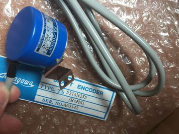
TS1526N55
TS3692N103
TS3624N2E3
TS3624N23E5
TS2014N311E32
TS3617N2E7
TS4509N2405E200
TS3275N125
TS1562N102
TS3692N41
TS3653N13E9
TS2014N18E32
TS2014N312E32
TS3617N3E10
TS4509N7000E100
TS3153N15E18
TS1567N132
TS3692N42
TS3653N2E6
TS2014N43E31
TS2018N303E51
TS3617N3E8
TS4514N1021E200
TS3602N213E8
TS3699N112
TS3653N3E7
TS2058N21E1-A
TS20E12
TS3617N13E8
TS4514N1407E200
TS3602N233E8
STEP 7 automatically creates the technological object and instance DB when you insert the instruction. The instance
DB contains the parameters of the technological object.
2 In the SCL example, "PID_Compact_1" is the name of the instance DB. Setpoint of the PID controller in automatic mode. Default value: 0.0
Input IN Real Process value. Default value: 0.0
You must also set sPid_Cmpt.b_Input_PER_On = FALSE.
Input_PER IN Word Analog process value (optional). Default value: W#16#0
You must also set sPid_Cmpt.b_Input_PER_On = TRUE.
ManualEnable IN Bool Enables or disables the manual operation mode. Default value: FALSE:
? PID_Compact V1.0 and V1.2: When the CPU transitions to RUN, if
the ManualEnable = TRUE, PID_Compact starts in manual mode. It
is not necessary for a FALSE to TRUE transition to place the
PID_Compact into manual mode.
? PID_Compact V1.1: When the CPU transitions to RUN and the
ManualEnable = TRUE, the PID Compact starts in the last state. A
transition from TRUE to FALSE to TRUE is required to place the
PID_Compact in manual mode.
ManualValue IN Real Process value for manual operation. Default value: 0.0
Reset IN Bool The Reset parameter restarts the controller. Default value: FALSE
See the "Response to Reset" section below for PID_Compact V1.1 and
V1.0 Reset response diagrams.
ScaledInput OUT Real Scaled process value. Default value: 0.0
Output1 OUT Real Output value. Default value: 0.0
Output_PER1 OUT Word Analog output value. Default value: W#16#0
Output_PWM1 OUT Bool Output value for pulse width modulation. Default value: FALSE
SetpointLimit_H OUT Bool Setpoint high limit. Default value: FALSE
If SetpointLimit_H = TRUE, the absolute upper limit of the setpoint is
reached. Default value: FALSE
SetpointLimit_L OUT Bool Setpoint low limit. Default value: FALSE
If SetpointLimit_L = TRUE, the absolute lower limit of the setpoint is
reached. Default value: FALSE
InputWarning_H OUT Bool If InputWarning_H = TRUE, the process value reached or exceeded the
upper warning limit. Default value: FALSE
InputWarning_L OUT Bool If InputWarning_L = TRUE, the process value reached the lower
warning limit. Default value: FALSE
State OUT Int Current operating mode of the PID controller. Default value: 0
Use sRet.i_Mode to change the mode.
? State = 0: Inactive
? State = 1: Pretuning
? State = 2: Manual fine tuning
? State = 3: Automatic mode
? State = 4: Manual mode
ErrorBits OUT DWord The PID_Compact instruction ErrorBits parameters table (Page 354)
defines the error messages. Default value: DW#16#0000 (no error)
1 The outputs of the Output, Output_PER, and Output_PWM parameters can be used in parallel. The response to Reset = TRUE depends on the version of the PID_Compact instruction.
Reset response PID_Compact V1.1
A rising edge at Reset resets the errors and warnings and clears the integral action. A falling
edge at Reset triggers a change to the most recently active operating mode. The response to Reset = TRUE depends on the version of the PID_Compact instruction.
Reset response PID_Compact V1.1
A rising edge at Reset resets the errors and warnings and clears the integral action. A falling
edge at Reset triggers a change to the most recently active operating mode. The response to Reset = TRUE depends on the version of the PID_Compact instruction.
Reset response PID_Compact V1.1
A rising edge at Reset resets the errors and warnings and clears the integral action. A falling
edge at Reset triggers a change to the most recently active operating mode. Incorrect configuration of output value limits.
Check to see if the limits of the output value are configured correctly and
match the direction in which the control is operating.
0100 Error during controller tuning has resulted in invalid parameters.
0200 Invalid value at parameter "Input": Numerical format of value is invalid.
0400 Calculating the output value failed. Check the PID parameters.
0800 Sampling time error: PID_Compact is not called within the sampling time of
the cyclic interrupt OB.
1000 Invalid value at parameter "Setpoint": Numerical format of value is invalid.
STEP 7 automatically creates the technological object and instance DB when you insert the instruction. The instance
DB contains the parameters of the technological object.
2 In the SCL example, "PID_3Step_1" is the name of the instance DB.
Table 9- 17 Data types for the parameters
Parameter and type Data type Description
Setpoint IN Real Setpoint of the PID controller in automatic mode. Default value: 0.0
Input IN Real Process value. Default value: 0.0
You must also set Config.InputPEROn = FALSE.
Input_PER IN Word Analog process value (optional). Default value: W#16#0
You must also set Config.InputPEROn = TRUE.
ManualEnable IN Bool Enables or disables the manual operation mode. Default value: FALSE
? On the edge of the change from FALSE to TRUE, the PID controller
switches to manual mode, State = 4, and Retain.Mode remains
unchanged.
? On the edge of the change from TRUE to FALSE, the PID controller
switches to the last active operating mode and
State = Retain.Mode. In manual mode, every rising edge opens the valve by 5% of the total
actuating range, or for the duration of the minimum motor actuation
time. ManualUP is evaluated only if you are not using Output_PER and
there is no position feedback. Default value: FALSE
? If Output_PER is FALSE, the manual input turns Output_UP on for
the time that corresponds to a movement of 5% of the device.
? If Config.ActuatorEndStopOn is TRUE, then Output_UP does not
come on if Actuator_H is TRUE.
ManualDN IN Bool In manual mode, every rising edge closes the valve by 5% of the total
actuating range, or for the duration of the minimum motor actuation
time. ManualDN is evaluated only if you are not using Output_PER and
there is no position feedback. Default value: FALSE
? If Output_PER is FALSE, the manual input turns Output_DN on for
the time that corresponds to a movement of 5% of the device.
? If Config.ActuatorEndStopOn is TRUE, then Output_DN does not
turn on if Actuator_L is TRUE.
ManualValue IN Real Process value for manual operation. Default value: 0.0
In manual mode, you specify the absolute position of the valve.
ManualValue is evaluated only if you are using OutputPer, or if position
feedback is available. Default value: 0.0
Feedback IN Real Position feedback of the valve. Default value: 0.0
To use Feedback, then set Config.FeedbackPerOn = FALSE.