|
| Place of Origin: | Japan |
| Brand Name: | Tamagawa |
| Certification: | CE |
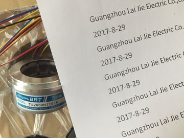
| Model Number: | TS5778N171 |
| Minimum Order Quantity: | 1pcs |
|---|---|
| Packaging Details: | carton |
| Delivery Time: | in stock |
| Payment Terms: | T/T, Western Union, MoneyGram |
| Supply Ability: | 100pcs/week |
| TS5778N171: | TS5778N171 | TAMAGAWA: | TAMAGAWA |
|---|---|---|---|
| WIRE: | Wire | Japan: | Japan |
| Color: | Black | Material: | Iron |
| Temperature: | 70 | Dimension: | 90mm |
TS5778N171
| outputs, as shown in the following | The TRCV_C instruction (Page 432) creates a communications connection to a partner station. The connection is set up, established, and automatically monitored until it is commanded to disconnect by the instruction. T |
| figureYou specify the parameters in the Properties configuration dialog of the TSEND_C instruction. |
The TRCV_C instruction combines the functions of the TCON, TDISCON, and TRCV instructions. |
| This dialog appears near the bottom of the page whenever you have selected any part of the TSEND_C instruction. T |
From the CPU configuration in STEP 7, you can configure how a TRCV_C instruction receives data. |
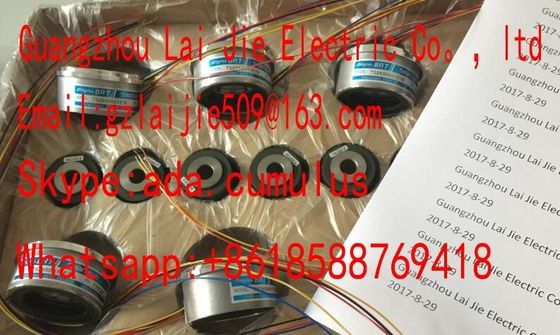
Guang Zhou Lai Jie Electric Co.,LTD
Please contact with “Tommy” for the price
TS4603N7002E200
TS4602N6321E100
TS3617N2E4
TS3617N13E9
TS4515N1202E200
TS3617N11E1
TS2014N182E32
TS1505N55
TS4515N6000E200
TS4603N1000E100
TS3617N2E5
TS3617N40E3
TS4515N2405E200
TS3617N1E3
TS2014N185E32
TS4602N1000E200
TS4603N1000E200
TS3617N2E6
TS5214N566
TS5205N450
TS5213N551
TS5208N122
TS5208N23
TS5778N171
TS5210N53
TS5320N510
TS5000N632
TS5212N510
TS5213N510
TS5312N616
TS208N101
TS5208N130
TS5213N530
TS5013N68
TS5214N566
TS5200N500
TS5305N616
TS5669N220
TS5214N564
TS5246N158
TS5667N650
To begin, insert the instruction into the program from the "Communications"
folder in the "Instructions" task card. The TRCV_C instruction is displayed, along with the
Call options dialog where you assign a DB for storing the parameters of the instruction. You can assign tag memory locations to the inputs and outputs, as shown in the following
figure: You specify the parameters in the Properties configuration dialog of the TRCV_C instruction.
This dialog appears near the bottom of the page whenever you have selected any part of the
TRCV_C instruction. INET IO device
In the "Devices and networks" portal, use the hardware catalog to add PROFINET IO
devices. For example, expand the following containers in the hardware catalog to add an ET200S IO
device: Distributed I/O, ET200S, Interface modules, and PROFINET. You can then select the
interface module from the list of ET200S devices (sorted by part number) and add the
ET200S IO device.
You can now connect the PROFINET IO device to the CPU:
1. Right-click the "Not assigned" link on the device and select "Assign new IO controller"
from the context menu to display the "Select IO controller" dialog.
2. Select your CPU (in this example, "PLC_1") from the list of IO controllers in the
project.
3. Click "OK" to create the network connection. After you configure the rack with the CPU, you are now ready to configure your network
connections.
In the "Devices and networks" portal, use the "Network view" to create the network
connections between the devices in your project. To create a PROFINET connection, click
the green (PROFINET) box on the first device, and drag a line to the PROFINET box on the
second device. Release the mouse button and your PROFINET connection is joined.
Refer to "Device Configuration: Creating a network connection" (Page 126) for more
information. Network connections between the devices also assign the PROFINET IO device to the CPU,
which is required for that CPU to control the device. To change this assignment, click the
PLC Name shown on the PROFINET IO device. A dialog box opens that allows the
PROFINET IO device to be disconnected from the current CPU and reassigned or left
unassigned, if desired.
The devices on your PROFINET network must have an assigned name before you can
connect with the CPU. Use the "Network view" to assign names to your PROFINET devices
if the devices have not already been assigned a name or if the name of the device is to be
changed. Right-click the PROFINET IO device, and select "Assign device name" to do this.
For each PROFINET IO device, you must assign the same name to that device in both the
STEP 7 project and, using the "Online & diagnostics" tool, to the PROFINET IO device
configuration memory (for example, an ET200 S interface module configuration memory). If
a name is missing or does not match in either location, the PROFINET IO data exchange
mode will not run. Refer to "Online and diagnostic tools: Assigning a name to a PROFINET
device online (Page 676)" for more informationIn a PROFINET network, each device must also have an Internet Protocol (IP) address. This
address allows the device to deliver data on a more complex, routed network:
● If you have programming or other network devices that use an on-board adapter card
connected to your plant LAN or an Ethernet-to-USB adapter card connected to an
isolated network, you must assign IP addresses to them. Refer to "Assigning IP
addresses to programming and network devices" (Page 132) for more information.
● You can also assign an IP address to a CPU or network device online. This is particularly
useful in an initial device configuration. Refer to "Assigning an IP address to a CPU
online" (Page 134) for more information.
● After you have configured your CPU or network device in your project, you can configure
parameters for the PROFINET interface, to include its IP address. Refer to "Configuring
an IP address for a CPU in your project" (Page 136) for more information. e IO cycle time
A PROFINET IO device is supplied with new data from the CPU within an "IO cycle" time
period. The update time can be separately configured for each device and determines the
time interval in which data is transmitted from the CPU to and from the device.
STEP 7 calculates the "IO cycle" update time automatically in the default setting for each
device of the PROFINET network, taking into account the volume of data to be exchanged
and the number of devices assigned to this controller. If you do not want to have the update