 |
| Place of Origin: | Japan |
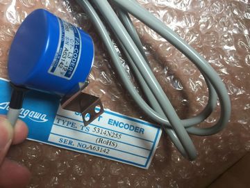
| Brand Name: | Tamagawa |
| Certification: | CE |
| Model Number: | TS5210N53 |
| Minimum Order Quantity: | 1pcs |
|---|---|
| Packaging Details: | carton |
| Delivery Time: | in stock |
| Payment Terms: | T/T, Western Union, MoneyGram |
| Supply Ability: | 100pcs/week |
| TAMAGAWA: | TAMAGAWA | TS5210N53: | TS5210N53 |
|---|---|---|---|
| Japan: | Japan | Color: | Black |
| Material: | Iron | Temperature: | 30-90 |
| Wire: | Wire |
TS5210N53
| time calculated automatically, you can change this setting. You specify the "IO cycle" parameters in the "Properties" configuration dialog of the PROFINET IO device. |
To ensure consistency between the send clock and the update time, |
| This dialog appears near the bottom of the page whenever you have selected any part of the instruction. |
"Realtime settings" ● "IO cycle" |
| In the "Device view" of the PROFINET IO device, click the PROFINET port. In the "PROFINET Interface" dialog, access the "IO cycle" parameters with the following menu selections: |
"Realtime settings" ● "IO cycle" |
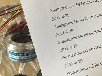
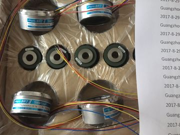
Guang Zhou Lai Jie Electric Co.,LTD
Please contact with “Tommy” for the price
TS5305N616
TS5669N220
TS5214N564
TS5246N158
TS5667N650
TS5213N551
TS5668N20
TS5667N120
TS5667N420
TS5246N160
TS5312N512
TS5208N122
TS5641N151
TS5270N15
TS5308N616
TS5213N510
TS2014N181E32
TS5308N616
TS3462N1E76
TS5214N561
TS5214N510
TS2014N182E32
TS3653N2E5
TS5320N510
TS5016N-60
TS5016N60
TS2651N111E78
TS2014N181E32
TS2651N131E78
TS2651N141E78
TS5214N566
TS5205N450
TS5308N616
TS3462N1E76
48-2500P8-L6-5V
TS5214N561
TS5214N510
TS2014N182E32
TS3653N2E5
TS5320N510
TS5016N-60
TS5016N60
TS2651N111E78
TS2014N181E32
TS5013N60,
TS5013N61,
TS5016N60,
TS5017N60,
TS5013N68,
TS5
013N69
TS5013N60
TS5016N60
TS5013N60
TS5016N60
TS5017N60
TS5013N68
TS5013N69
TS2014N181E32
TS2014N311E32
TS2650N11E78
TS2650N1E78
activate the "Adapt
update time when send clock changes" option. This option ensures that the update time
is not set to less than the send clock. rrupt organization block (OB82)
If a module with diagnostic capability with diagnostic interrupt enabled detects a change in its
diagnostic status, it sends a diagnostic interrupt request to the CPU for the following
situations:
● A problem has been detected by this module (for example, a wire break) or a component
requires maintenance or both (incoming event).
● The problem has been corrected or no longer exists, and no further components require
maintenance (outgoing event).
If OB82 does not exist, these errors are written to the diagnostics buffer. The CPU does not
take any action or switch to STOP.
If OB82 does exist, the operating system can call OB82 in response to an incoming event.
You must create OB82, and this OB allows you to configure local error handling and a more
detailed reaction to incoming events.
If you are using a DPV1 capable CPU, you can obtain additional information on the interrupt
with the help of the RALRM instruction, which provides more specific information than the
start information of OB82. These errors are written to the diagnostics buffer. The CPU does not take any action or
switch to STOP. Errors written to the diagnostics buffer include:
● Module faults
● Module mismatch
● Module missingThese errors are written to the diagnostics buffer. The CPU does not take any action or
switch to STOP.
10.2.8 Distributed I/O Instructions
Refer to "Distributed I/O (PROFINET, PROFIBUS, or AS-i)" (Page 274) for information on
how to use the distributed I/O instructions with these communication networks.
10.2.9 Diagnostic instructions
Refer to the "Diagnostics (PROFINET or PROFIBUS)": "Diagnostics instructions" (Page 297)
for information on how to use these instructions with these communication networks.
10.2.10 Diagnostic events for distributed I/O
Refer to the "Diagnostics (PROFINET or PROFIBUS)": "Diagnostics events for distributed
I/O" (Page 297) for information on how to use this diagnostic information with these
communication networks.
10.3 PROFIBUS
A PROFIBUS system uses a bus master to poll slave devices distributed in a multi-drop
fashion on an RS485 serial bus. A PROFIBUS slave is any peripheral device (I/O
transducer, valve, motor drive, or other measuring device) which processes information and
sends its output to the master. The slave forms a passive station on the network since it
does not have bus access rights, and can only acknowledge received messages, or send
response messages to the master upon request. All PROFIBUS slaves have the same
priority, and all network communication originates from the master.
A PROFIBUS master forms an "active station" on the network. PROFIBUS DP defines two
classes of masters. A class 1 master (normally a central programmable controller (PLC) or a
PC running special software) handles the normal communication or exchange of data with
the slaves assigned to it. A class 2 master (usually a configuration device, such as a laptop
or programming console used for commissioning, maintenance, or diagnostics purposes) is
a special device primarily used for commissioning slaves and for diagnostic purposes. The is connected to a PROFIBUS network as a DP slave with the CM 1242-5
communication module. The CM 1242-5 (DP slave) module can be the communications
partner of DP V0/V1 masters. In the figure below, the is a DP slave to an S7-300
controllerThe is connected to a PROFIBUS network as a DP master with the CM 1243-5
communication module. The CM 1243-5 (DP master) module can be the communications
partner of DP V0/V1 slaves. In the figure below, the is a master controlling an
ET200S DP slave. If a CM 1242-5 and a CM 1243-5 are installed together, an can perform as both a
slave of a higher-level DP master system and a master of a lower-level DP master system,
simultaneouslyFor V3.0, you can configure a maximum of three PROFIBUS CMs per station, in which there
can be any combination of DP master or DP slave CMs. DP masters in a V3.0
implementation can each control a maximum of 32 slaves.
For V2.2, you can configure a maximum of three PROFIBUS CMs per station, of which only
one may be a DP master. A DP master in a V2.2 implementation can control a maximum of
16 slaves. to PROFIBUS DP
The can be connected to a PROFIBUS fieldbus system with the following
communications modules:
● CM 1242-5
Operates as DP slave
● CM 1243-5
Operates as DP master class 1
If a CM 1242-5 and a CM 1243-5 are installed together, an can perform the
following tasks simultaneously:
● Slave of a higher-level DP master system
and
● Master of a lower-level DP master system
10.3.1.2 Communications services of the PROFIBUS CMs
Bus protocol
The PROFIBUS CMs use the PROFIBUS DP-V1 protocol. he following types of communication are available with DP-V1:
● Cyclic communication (CM 1242-5 and CM 1243-5)
Both PROFIBUS modules support cyclic communication for the transfer of process data
between DP slave and DP master.
Cyclic communication is handled by the operating system of the CPU. No software blocks
are required for this. The I/O data is read or written directly from/to the process image of
the CPU.