|
| Place of Origin: | Japan |
| Brand Name: | Tamagawa |
| Certification: | CE |
| Model Number: | TS5320N510 |
| Minimum Order Quantity: | 1pcs |
|---|---|
| Packaging Details: | carton |
| Delivery Time: | in stock |
| Payment Terms: | T/T, Western Union, MoneyGram |
| Supply Ability: | 100pcs/week |
| TAMAGAWA: | TAMAGAWA | TS5320N510: | TS5320N510 |
|---|---|---|---|
| Japan: | Japan | Color: | Black |
| Material: | Iron | Temperature: | 20-90 |
| Wire: | Wire |
TS5320N510
| In the Devices and Networks portal, use the "Network view" to create the network connections between the devices in your project. |
Drag a line to the AS-i box on the second device. Release the mouse button and your AS-i connection is joined |
| To create the AS-i connection, select the | Refer to "Device Configuration: Creating a network connection" (Page 126) for more |
| yellow (AS-i) box on the first device | information. To configure parameters for the AS-i interface, click the yellow AS-i box on the AS-i master |
Guang Zhou Lai Jie Electric Co.,LTD
Please contact with “Tommy” for the price
TS5013N60
TS5016N60
TS5013N60
TS5016N60
TS5017N60
TS5013N68
TS5013N69
TS2014N181E32
TS2014N311E32
TS2650N11E78
TS2650N1E78
TS5081N1
TS5084N250
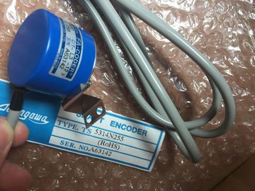
TS5314N255
TS5303N510
TS5622N131
TS1616N200
TS1501N13
TS5641N154
TS5205N454
TS5668N20
TS5667N120
TS5667N420
TS5308N616
TS3462N1E76
TS5214N561
TS5214N510
TS2014N182E32
TS3653N2E5
TS5320N510
TS5016N60
TS5016N60
TS2651N111E78
TS2014N181E32
TS5208N130
TS5214N566
TS5205N450
TS5205N454
TS2651N11E78
TS2651N141E78
TS2651N1E78
TS2651N131E78
TS3103N40
CM1243-2 module, and the "Properties" tab in the inspector window displays the AS-i
interface.
In the STEP 7 inspector window, you can view, configure, and change general information,
addresses and operating parameters:
Table 10- 40 AS-i master CM1243-2 module properties General Name of the AS-i master CM 1243-2
Operating parameters Parameters for the response of the AS-i master
I/O addresses Address area for the slave I/O addresses
AS-i interface (X1) Assigned AS-i network
Note
"Diagnostic interrupt for faults in the AS-i configuration" and "Automatic address
programming" are always active and are therefore shown in gray.To configure parameters for the AS-i interface, click the yellow AS-i box on the AS-i slave,
and the "Properties" tab in the inspector window displays the AS-i interface.In an AS-i network, each device is assigned an AS-i slave address. This address can range
from 0 through 31; however, address 0 is reserved only for new slave devices.
The slave addresses are 1(A or B) to 31(A or B) for a total of up to 62 slave devices. Any
address in the range of 1 - 31 can be assigned to an AS-i slave device; in other words, it
does not matter whether the slaves begin with address 21 or whether the first slave is
actually given the address 1.
Enter the AS-i slave address here. The AS-i master reserves a 62-byte data area in the I/O area of the CPU. Access to the
digital data is performed here in bytes; for each slave, there is one byte of input and one byte
of output data. The assignment of the AS-i connections of the AS-i digital slaves to the data bits of the
assigned byte is indicated in the inspection window of the AS-i master CM 1243-2You can access the data of the AS-i slaves in the user program by using the displayed I/O
addresses with the appropriate bit logic operations (for example, "AND") or bit assignments.
Note
"System assignment" is automatically activated if you do not configure the AS-i slaves with
STEP 7.
If you do not configure any slaves, you must inform the AS-i master CM1243-2 about the
actual bus configuration using the online function "ACTUAL > EXPECTED". You can find detailed information on the AS-i master CM 1243-2 in the "AS-i master CM
1243-2 and AS-i data decoupling unit DCM 1271 for SIMATIC " Manual
The CPU accesses the digital inputs and outputs of the AS-i slaves through the AS-i master
CM1243-2 in cyclic operation. The data is accessed through I/O addresses or by means of a
data record transfer. AS-i slave address 1
② AS-i slave address 2A
③ AS-i slave address 3
Access to the digital data is performed here in bytes (in other words, one byte is assigned to
each AS-i digital slave). When you configure the AS-i slaves in STEP 7, the I/O address for
accessing the data from the user program is displayed in the inspection window for the
respective AS-i slave.
The digital input module (AS-i SM-U, 4DI) in the AS-i network above has been assigned
slave address 1. By clicking on the digital input module, the "AS interface" tab in the device
"Properties" displays the slave address, as shown below: The digital input module (AS-i SM-U, 4DI) in the AS-i network above has been assigned I/O
address 2. By clicking on the digital input module, the "I/O addresses" tab in the device
"Properties" displays the I/O address, as shown below: You can access the data of the AS-i slaves in the user program by using their I/O addresses
with the appropriate bit logic operations (for example, "AND") or bit assignments. The
following simple program illustrates how the assignment works:
Input 2.0 is polled in this program. In the AS-i system, this input belongs to slave1 (Input byte
2, bit 0). Output 4.3, which is then set, corresponds to AS-i slave 3 (Output byte 4, bit 3)You can access analog data of an AS-i slave through the process image of the CPU if you
have configured this AS-i slave in STEP 7 as an analog slave.
If you did not configure the analog slave in STEP 7, you can only access the data of the AS-i
slave through the acyclic functions (data record interface). In the user program of the CPU,
AS-i calls are read and written using the RDREC (read data record) and WRREC (write data
record) distributed I/O instructions. A configuration of the AS-i slaves specified through STEP 7 and downloaded into the S7
station is transferred by the CPU on the AS-i master CM1243-2 during S7 station start-up.
Any existing configuration that was determined through the "System assignment" online
function (Page 484) ("ACTUAL -> EXPECTED") will be overwritten.tion
You can find detailed information on the AS-i master CM 1243-2 in the "AS-i master CM
1243-2 and AS-i data decoupling unit DCM 1271 for SIMATIC " Manual
Refer to "Distributed I/O (PROFINET, PROFIBUS, or AS-i)" (Page 274) for information on
how to use the distributed I/O instructions with these communication networks. You must go online to view and change the AS-i operational modes.
In order to go online, your must first be in "Device configuration" with the AS-i master
CM1243-2 module selected, and then click the "Go online" button in the toolbar. Next, select
the "Online and diagnostics" command from the "Online" menuThere are two AS-i operational modes:
● Protection mode:
– You cannot change AS-i slave device and CPU I/O addresses.
– The green "CM" LED is OFF.
● Configuration mode:
TS3653N2E5
TS3653N3E8
TS3684N1E3
TS3684N2E6
TS3684N3E8
TS3667N3E8
TS3624N2E3
TS3624N2E4
TS3624N3E6
TS3630N1E1
TS3630N2E3
TS3630N1306
TS3630N1303E9