|
| Place of Origin: | Japan |
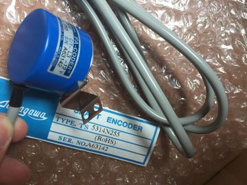
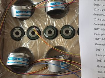
| Brand Name: | Tamagawa |
| Certification: | CE |
| Model Number: | TS5213N530 |
| Minimum Order Quantity: | 1pcs |
|---|---|
| Packaging Details: | carton |
| Delivery Time: | in stock |
| Payment Terms: | T/T, Western Union, MoneyGram |
| Supply Ability: | 100pcs/week |
| TAMAGAWA: | TAMAGAWA | Material: | Iron |
|---|---|---|---|
| TS5213N530: | TS5213N530 | Color: | Black |
| Japan: | Japan | Temperature: | 20-90 |
| Dimension: | 50mm | Wire: | Wire |
TS5213N530
| For RS485 mode, there is only one operating mode. The different selections for Receive line initial state reference the cases shown below for more details. | Select forward bias to use internal bias and termination |
| Half duplex (RS485) two wire mode. In the Receive line initial state: | ● Mode of operation: RS485 |
| – Select none when you supply the bias and termination (Case 5). | Receive line initial state: Forward bias (biased with R(B) > R(A) > 0V) |
Guang Zhou Lai Jie Electric Co.,LTD
Please contact with “Tommy” for the price
TS3617N3E9
TS3617N13E9
TS3617N40E3
TS3617N47E4
TS3624N1E1
TS3624N21E1
TS3624N21E2
TS3624N1E2
TS3624N102E4
TS3624N103E5
TS3624N203E5
TS3624N22E4
TS3624N23E5
TS3624N2E3
TS3624N2E4
TS3624N3E5
TS3624N3E6
TS3630N1303E9
TS3630N1309E5
TS3630N1306
TS3630N1E1
TS3630N1E2
TS3630N2E3
TS3630N2E4
TS3630N3E5
TS3630N101E2
TS3630N102E4
TS3630N22E3
TS3630N22E4
TS3631N1E1
TS3636N6
TS3641N1E1
TS3641N21E6
TS3641N22E7
TS3641N2E3
TS3641N12E3
● Mode of operation: RS485 ● Receive line initial state: No bias (external bias required)
The example program uses a global data block for the communication buffer, a RCV_PTP instruction (Page 578) to receive data from the terminal emulator, and a SEND_PTP instruction (Page 575) to echo the buffer back to the terminal emulator. To program the example, add the data block configuration and program OB1 as described below. Global data block "Comm_Buffer": Create a global data block (DB) and name it "Comm_Buffer". Create one value in the data block called "buffer" with a data type of "array [0 .. 99] of byte". Network 1: Enable the RCV_PTP instruction whenever SEND_PTP is not active. Tag_8 at MW20.0 indicates when sending is complete in Network 4, and when the communication module is thus ready to receive a message. The example program uses a global data block for the communication buffer, a RCV_PTP instruction (Page 578) to receive data from the terminal emulator, and a SEND_PTP instruction (Page 575) to echo the buffer back to the terminal emulator. To program the example, add the data block configuration and program OB1 as described below. Global data block "Comm_Buffer": Create a global data block (DB) and name it "Comm_Buffer". Create one value in the data block called "buffer" with a data type of "array [0 .. 99] of byte". Network 1: Enable the RCV_PTP instruction whenever SEND_PTP is not active. Tag_8 at MW20.0 indicates when sending is complete in Network 4, and when the communication module is thus ready to receive a message.
Enable the SEND_PTP instruction when the M20.0 flag is set. Also use this flag to set the REQ input to TRUE for one scan. The REQ input tells the SEND_PTP instruction that a new request is to be transmitted. The REQ input must only be set to TRUE for one execution of SEND_PTP. The SEND_PTP instruction is executed every scan until the transmit completes. The transmit is complete when the last byte of the message has been transmitted from the CM 1241. When the transmit is complete, the DONE output (Tag_5 at M10.0) is set TRUE for one execution of SEND_PTP.
You must set up the terminal emulator to support the example program. You can use most any terminal emulator on your PC, such as HyperTerminal. Make sure that the terminal emulator is in the disconnected mode before editing the settings as follows: 1. Set the terminal emulator to use the RS232 port on the PC (normally COM1). 2. Configure the port for 9600 baud, 8 data bits, no parity (none), 1 stop bit and no flow control. 3. Change the settings of the terminal emulator to emulate an ANSI terminal. 4. Configure the terminal emulator ASCII setup to send a line feed after every line (after the user presses the Enter key). 5. Echo the characters locally so that the terminal emulator displays what is typed.
To exercise the example program, follow these steps: 1. Download the STEP 7 program to the CPU and ensure that it is in RUN mode. 2. Click the "connect" button on the terminal emulator to apply the configuration changes and open a terminal session to the CM 1241. 3. Type characters at the PC and press Enter. The terminal emulator sends the characters to the CM 1241 and to the CPU. The CPU program then echoes the characters back to the terminal emulator.