|
| Place of Origin: | Japan |
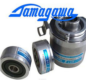
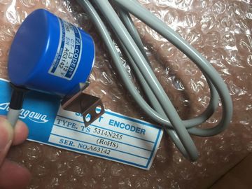
| Brand Name: | Tamagawa |
| Certification: | CE |
| Model Number: | TS5641N151 |
| Minimum Order Quantity: | 1pcs |
|---|---|
| Packaging Details: | carton |
| Delivery Time: | in stock |
| Payment Terms: | T/T, Western Union, MoneyGram |
| Supply Ability: | 100pcs/week |
| TAMAGAWA: | TAMAGAWA | Japan: | Japan |
|---|---|---|---|
| Color: | Black | TS5641N151: | TS5641N151 |
| Material: | Iron | Wire: | Wire |
| Dimension: | 50mm | Temperature: | 30-90 |
TS5641N151
| locity". ③ Travel to reference point position (green curve segment): After homing at the reference point switch, the axis travels |
Note If the homing search does not function as you expected, check the inputs assigned to the hardware limits or to the reference point. |
| to the "Reference point coordinates" at the "reduced velocity". On reaching the "Reference point coordinates", | These inputs may have had their edge interrupts disabled in device configuration. |
| the axis is stopped at the position value that was specified in the Position input parameter of the MC_Home instruction". |
Examine the configuration data for the axis technology object of concern to see which inputs (if any) are assigned for "HW Low Limit Switch Input", |
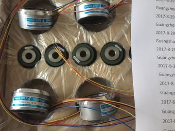
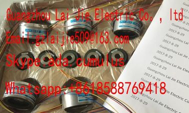
Guang Zhou Lai Jie Electric Co.,LTD
Please contact with “Tommy” for the price
TS3630N1E1
TS5013N61
TS2651N111E78
TS4127N1017E215
TS1982N126E6
TS3653N44E8
TS3630N1E2
TS5013N89
TS2651N181E78
TS4127N1017E235
TS1982N128E6
8001231S
TS3653N4E12
TS5013N64
TS3630N2E3
TS5016N
TS5000N532
TS4231N6E17
TS1982N53E6
800123-2R
TS3653N14E12
TS5420N60
TS3630N2E4
TS5016N60
TS5000N632
TS4231N6E17
TS1982N56E18
TS3653N58E5
TS5778N155
TS3630N3E5
TS5003N632
TS4244N10E24
TS1982N56E18
800123-R-F
TS3653N65E27
TS5208N23
TS3630N101E2
TS5017N56
HW High Limit Switch Input", and
"Input reference point switch". Then open the Device configuration for the CPU and examine
each of the assigned inputs. Verify the "Enable rising edge detection" and "Enable falling
edge detection" are both selected. If these properties are not selected, delete the specified
inputs in the axis configuration and select them agaiWith the jerk limit you can reduce the stresses on your mechanics during an acceleration
and deceleration ramp. The value for the acceleration and deceleration is not changed
abruptly when the step limiter is active; it is adapted in a transition phase. The figure below
shows the velocity and acceleration curve without and with jerk limitThe jerk limit gives a "smoothed" velocity profile of the axis motion. This ensures soft starting
and braking of a conveyor belt for example. The axis is enabled and ready to be controlled via motion control tasks.
(Tag of technology object: <Axis name>.StatusBits.Enable)
Homed The axis is homed and is capable of executing absolute positioning tasks of motion control
instruction "MC_MoveAbsolute". The axis does not have to be homed for relative homing. Special
situations:
During active homing, the status is FALSE.
If a homed axis undergoes passive homing, the status is set to TRUE during passive homing.
(Tag of technology object: <Axis name>.StatusBits.HomingDone)
Error An error has occurred in the "Axis" technology object. More information about the error is available
in automatic control at the ErrorID and ErrorInfo parameters of the motion control instructions. In
manual mode, the "Last error" field of the control panel displays detailed information about the
cause of error.
(Tag of technology object: <Axis name>.StatusBits.Error)
Control panel active The "Manual control" mode was enabled in the control panel. The control panel has control priority
over the "Axis" technology object. The axis cannot be controlled from the user program.
(Tag of technology object: <Axis name>.StatusBits.ControlPanelActive)
Table 9- 55 Drive status
Status Description
Drive ready The drive is ready for operation.
(Tag of technology object: <Axis name>.StatusBits.DriveReady)
Error The drive has reported an error after failure of its ready signal.
(Tag of technology object: <Axis name>.ErrorBits.DriveFault)The axis is at a standstill.
(Tag of technology object: <Axis name>.StatusBits.StandStill)
Accelerating The axis accelerates.
(Tag of technology object: <Axis name>.StatusBits.Acceleration)The axis travels at constant velocity.
(Tag of technology object: <Axis name>.StatusBits.ConstantVelocity)
Decelerating The axis decelerates (slows down).
(Tag of technology object: <Axis name>.StatusBits.Deceleration)
Table 9- 57 Status of the motion mode
Status Description