 |
| Place of Origin: | Japan |
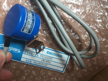
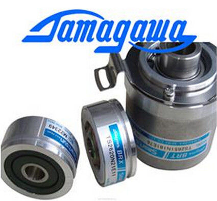
| Brand Name: | Tamagawa |
| Certification: | CE |
| Model Number: | TS5213N510 |
| Minimum Order Quantity: | 1pcs |
|---|---|
| Packaging Details: | carton |
| Delivery Time: | in stock |
| Payment Terms: | T/T, MoneyGram,, Western Union |
| Supply Ability: | 100pcs/week |
| TAMAGAWA: | TAMAGAWA | Material: | Iron |
|---|---|---|---|
| TS5213N510: | TS5213N510 | Color: | Black |
| Japan: | Japan | Wire: | Wire |
| Dimension: | 70mm | Temperature: | 30-90 |
TS5213N510
| Configuration of homing parameters | mechanical endstop in the event of a direction reversal: |
| Configure the parameters for active and passive homing in the "Homing" configuration | |
| indow. The homing method is set using the "Mode" input parameter of the motion control | instruction. Here, Mode = 2 means passive homing and Mode = 3 means active homing. Use one of the following measures to ensure that the machine does not travel to a |
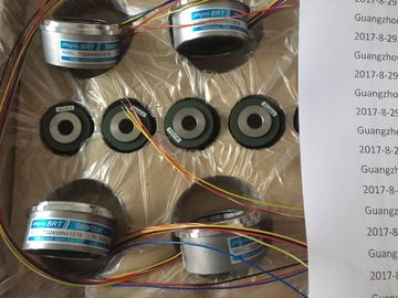
Guang Zhou Lai Jie Electric Co.,LTD
Please contact with “Tommy” for the price
TS5210N450
TS4503N1202E200
TS3103N178
TS3664N2E4
TS5013N61
TS3641N2E3
TS5212N351
TS5210N453
TS4503N1205E200
TS3103N255
TS3664N50
TS5016N60
TS3641N12E3
TS5212N510
TS5210N458
TS4503N1828E100
TS3103N302
OAH14BSD
TS3667N1E2
TS5013N63
TS3641N32
TS5213N550
TS5210N530
TS4503N2000E100
TS3103N40
OAS66
TS3667N11E2
TS5016N61
TS3641N38
TS5213N551
TS5210N54
TS4503N2070E100
TS3132N32
OAS66
TS1857N16EP
TS3667N2E5
TS5016N63
TS3643N2
TS5308N510
TS20E12
Keep the approach velocity low
Increase the configured acceleration/deceleration
Increase the distance between hardware limit switch and mechanical stop Select the digital input for the reference point switch from the drop-down list box. The
input must be interrupt-capable. The onboard CPU inputs and inputs of an inserted
signal board can be selected as inputs for the reference point switch.
The default filter time for the digital inputs is 6.4 ms. When the digital inputs are used
as a reference point switch, this can result in undesired decelerations and thus
inaccuracies. Depending on the reduced velocity and extent of the reference point
switch, the reference point may not be detected. The filter time can be set under
"Input filter" in the device configuration of the digital inputs.
The specified filter time must be less than the duration of the input signal at the
reference point switch.
Auto reverse after reaching the
hardware limit switches
(Active homing only)
Activate the check box to use the hardware limit switch as a reversing cam for the
reference point approach. The hardware limit switches must be configured and
activated for direction reversal.
If the hardware limit switch is reached during active homing, the axis brakes at the
configured deceleration (not with the emergency deceleration) and reverses direction.
The reference point switch is then sensed in reverse direction.
If the direction reversal is not active and the axis reaches the hardware limit switch
during active homing, the reference point approach is aborted with an error and the
axis is braked at the emergency deceleration.
Approach direction
(Active and passive homing)
With the direction selection, you determine the "approach direction" used during
active homing to search for the reference point switch, as well as the homing
direction. The homing direction specifies the travel direction the axis uses to
approach the configured side of the reference point switch to carry out the homing
operation.
Reference point switch
(Active and passive homing)
Active homing: Select whether the axis is to be referenced on the left or right side
of the reference point switch. Depending on the start position of the axis and the
configuration of the homing parameters, the reference point approach sequence
can differ from the diagram in the configuration window.
Passive homing: With passive homing, the traversing motions for purposes of
homing must be implemented by the user via motion commands. The side of the
reference point switch on which homing occurs depends on the following factors:
– "Approach direction" configuration
– "Reference point switch" configuration
– Current travel direction during passive homing
Approach velocity