 |
| Place of Origin: | Japan |
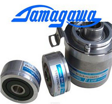
| Brand Name: | Tamagawa |
| Certification: | CE |
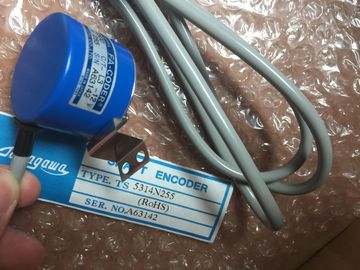
| Model Number: | TS5214N561 |
| Minimum Order Quantity: | 1pcs |
|---|---|
| Packaging Details: | carton |
| Delivery Time: | in stock |
| Payment Terms: | T/T, Western Union, MoneyGram |
| Supply Ability: | 100pcs/week |
| TAMAGAWA: | TAMAGAWA | Material: | Iron |
|---|---|---|---|
| Color: | Black | Japan: | Japan |
| TS5214N561: | TS5214N561 | Wire: | Wire |
| Temperature: | 30-90 | Dimension: | 50mm |
TS5214N561
| Based upon the user’s selection while the CPU is in RUN mode, either the values stored in the image register or the pulse generator outputs drive the digital outputs. |
cannot be used in the CPU 1211C. |
| Table 9- 48 Address assignments of the pulse and direction outputs The CPU 1211C does not have outputs Q0.4, Q0.5, Q0.6, or Q0.7. | |
| In STOP mode, the PTO generator does not control the outputs. |
The CPU 1212C does not have outputs Q0.6 or Q0.7. Therefore, these outputs cannot be used in the CPU 1212C. |
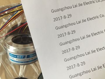
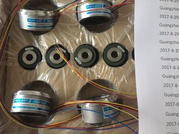
Guang Zhou Lai Jie Electric Co.,LTD
Please contact with “Tommy” for the price
TS5214N561
3 This table applies to the CPU 1211C, CPU 1212C, CPU 1214C, and CPU 1215C PTO functions
For motion control, you can optionally configure a drive interface for "Drive enabled" and
"Drive ready". When using the drive interface, the digital output for the drive enable and the
digital input for "drive ready" can be freely selected. The firmware will take control via the corresponding pulse and direction outputs if the PTO
(Pulse Train Output) has been selected and assigned to an axis.
With this takeover of the control function, the connection between the process image and I/O
output is also disconnected. While the user has the possibility of writing the process image of
pulse and direction outputs via the user program or watch table, this is never transferred to
the I/O output. Accordingly, it is also not possible to monitor the I/O output via the user
program or watch table. The information read merely reflects the value of the process image
and does not match the actual status of the I/O output in any respect.
For all other CPU outputs that are not used permanently by the CPU firmware, the status of
the I/O output can be controlled or monitored via the process image, as usualUse the hardware and software limit switches to limit the "allowed travel range" and the
"working range" of your axisMechanical stop A Allowed travel range for the axis
② Lower and upper hardware limits B Working range of the axis
③ Lower and upper software limits C Distance
Hardware and software limit switches must be activated prior to use in the configuration or in
the user program. Software limit switches are only active after homing the axis. Hardware limit switches determine the maximum travel range of the axis. Hardware limit
switches are physical switching elements that must be connected to interrupt-capable inputs
of the CPU. Use only hardware limit switches that remain permanently switched after being
approached. This switching status may only be revoked after a return to the allowed travel
rangWhen the hardware limit switches are approached, the axis brakes to a standstill at the
configured emergency deceleration. The specified emergency deceleration must be
sufficient to reliably stop the axis before the mechanical stop. The following diagram
presents the behavior of the axis after it approaches the hardware limit switches. If the filter time for a digital input channel is changed from a previous setting, a new "0"
level input value may need to be presented for up to 20.0 ms accumulated duration before
the filter becomes fully responsive to new inputs. During this time, short "0" pulse events of
duration less than 20.0 ms may not be detected or counted.