|
| Place of Origin: | Japan |
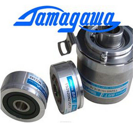
| Brand Name: | Tamagawa |
| Certification: | CE |
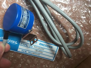
| Model Number: | TS5214N510 |
| Minimum Order Quantity: | 1pcs |
|---|---|
| Packaging Details: | carton |
| Delivery Time: | in stock |
| Payment Terms: | T/T, Western Union, MoneyGram |
| Supply Ability: | 100pcs/week |
| TAMAGAWA: | TAMAGAWA | Material: | Iron |
|---|---|---|---|
| TS5214N510: | TS5214N510 | Color: | Black |
| Japan: | Japan | Temperature: | 20-90 |
| Wire: | Wire | Dimension: | 50mm |
TS5214N510
The technology object TO_Axis_PTO V2.0 must be correctly configured.
| The technology object TO_Axis_PTO V2.0 must be correctly configured. | RampUpTime IN Real Time (in seconds) to accelerate from standstill to the configured |
| The technology object TO_CommandTable_PTO must be correctly configured. | maximum velocity without jerk limit. Default value: 5.00 |
| The axis must be released. TRUE = Change ramp-up time in line with input parameter "RampUpTime". Default value: FALSE |
The change will influence the tag <Axis name>. |
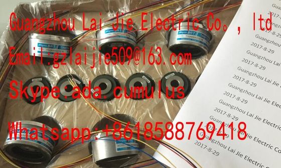
Guang Zhou Lai Jie Electric Co.,LTDThe change will influence the tag <Axis name>.
Please contact with “Tommy” for the price
TS4507N8029E200
TS3214N44
TS1446N4
TS3684N13E8
TS3664N2E4
TS3624N102E4
TS16N13E12
TS3103N5037
TS4509N1002E200
TS3218
TS1508N202
TS3684N1E3
TS3653N13E7
TS3624N103E5
TS16N18E11
TS3501N
TS4509N1202E200
TS3218N42
TS1508N77
TS3684N2E6
TS3653N12E6
TS3624N203E5
TS2013N191E26
TS3510N39E10
TS4509N1831E200
TS3218N5
TS1508N85
TS3684N3E8
TS3653N2E5
Config.DynamicDefaults.Acceleration. The effectiveness of the
change is shown in the description of this tag.
ChangeRampDown IN Bool TRUE = Change ramp-down time in line with input parameter
"RampDownTime". Default value: FALSE
RampDownTime IN Real Time (in seconds) to decelerate axis from the configured
maximum velocity to standstill without jerk limiter. Default value:
5.00
The change will influence the tag <Axis name>.
Config.DynamicDefaults.Deceleration. The effectiveness of the
change is shown in the description of this tag.
ChangeEmergency IN Bool TRUE = Change emergency stop ramp-down time in line with
input parameter "EmergencyRampTime" Default value: FALSE
EmergencyRampTime IN Real Time (in seconds) to decelerate the axis from configured
maximum velocity to standstill without jerk limiter in emergency
stop mode. Default value: 2.00
The change will influence the tag <Axis name>.
Config.DynamicDefaults.EmergencyDeceleration. The
effectiveness of the change is shown in the description of this
tag.
ChangeJerkTime IN Bool TRUE = Change smoothing time according to the input
parameter "JerkTime". Default value: FALSE
JerkTime IN Real Smoothing time (in seconds) used for the axis acceleration and
deceleration ramps. Default value: 0.25
The change will influence the tag <Axis name>.
Config.DynamicDefaults.Jerk. The effectiveness of the change is
shown in the description of this tag.
Done OUT Bool TRUE = The changed values have been written to the
technology data block. The description of the tags will show
when the change becomes effective. Default value: FALSE
Error OUT Bool TRUE = An error occurred during execution of the command.
The cause of the error can be found in parameters "ErrorID" and
"ErrorInfo". Default value: FALSE
ErrorID OUT Word Error identifier. Default value: 16#0000
ErrorInfo IN Word Error information. Default value: 16#0000
Prerequisites for MC_ ChangeDynamic execution:
● The technology object TO_Axis_PTO V2.0 must be correctly configured.
● The axis must be released.
Override response
An MC_ChangeDynamic command cannot be aborted by any other Motion Control
A new MC_ChangeDynamic command does not abort any active Motion Control jobs.
Note
The input parameters "RampUpTime", "RampDownTime", "EmergencyRampTime" and
"RoundingOffTime" can be specified with values that makes the resultant axis parameters
"acceleration", "delay", "emergency stop-delay" and "jerk" outside the permissible limits.
Make sure you keep the MC_ChangeDynamic parameters within the limits of the dynamic
configuration settings for the axis technological object. The CPU provides four pulse output generators. Each pulse output generator provides one
pulse output and one direction output for controlling a stepper motor drive or a servo motor
drive with pulse interface. The pulse output provides the drive with the pulses required for
motor motion. The direction output controls the travel direction of the drive.
Pulse and direction outputs are permanently assigned to one another. Onboard CPU outputs
and outputs of a signal board can be used as pulse and direction outputs. You select
between onboard CPU outputs and outputs of the signal board during device configuration
under Pulse generators (PTO/PWM) on the "Properties" tab. Only PTO (Pulse Train Output)
applies to motion control.
The PTO output generates a square wave output of variable frequency. Pulse generation is
controlled by configuration and execution information supplied through H/W configuration
and/or SFCs/SFBs.