 |
| Place of Origin: | Japan |
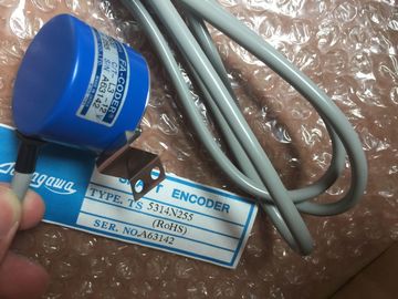
| Brand Name: | Tamagawa |
| Certification: | CE |
| Model Number: | TS5016N60 |
| Minimum Order Quantity: | 1pcs |
|---|---|
| Packaging Details: | carton |
| Delivery Time: | in stock |
| Payment Terms: | T/T, Western Union, MoneyGram |
| Supply Ability: | 100pcs/week |
| TAMAGAWA: | TAMAGAWA | Material: | Iron |
|---|---|---|---|
| Color: | Black | Japan: | Japan |
| TS5016N60TS5016N60: | TS5016N60 | Dimension: | 40mm |
| Temperature: | 20-90 |
TS5016N60
| More information on SMTP error codes can be found on the internet or in the error documentation for the mail server. |
STOP/RUN – Solid yellow indicates STOP mode |
| You can also read the last error message from the mail server. |
Solid green indicates RUN mode – Flashing (alternating green and yellow) indicates that the CPU is in STARTUP mode ● ERROR |
| The error message in stored in buffer1parameter of the instance DB for TM_MAILThe CPU provides the follog status indicators: |
Flashing red indicates an error, such as an internal error in the CPU, a error with the memory card, or a configuration error (mismatched modules) |
Guang Zhou Lai Jie Electric Co.,LTD
Please contact with “Tommy” for the price
TS2651N141E78
TS5214N566
TS5205N450
TS5308N616
TS3462N1E76
48-2500P8-L6-5V
TS5214N561
TS5214N510
TS2014N182E32
TS3653N2E5
TS5320N510
TS5016N-60
TS5016N60
TS2651N111E78
TS2014N181E32
TS5013N60,
TS5013N61,
TS5016N60,
TS5017N60,
TS5013N68,
TS5
013N69
TS5013N60
TS5016N60
TS5013N60
TS5016N60
TS5017N60
TS5013N68
TS5013N69
TS2014N181E32
TS2014N311E32
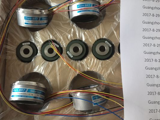
TS2650N11E78
TS2650N1E78
TS5081N1
TS5084N250
TS5314N255
TS5303N510
TS5622N131
TS1616N200
TS1501N13
TS5641N154
TS5205N454
TS5668N20
TS5667N120
TS5667N420
TS5308N616
TS3462N1E76
TS5214N561
TS5214N510
TS2014N182E32
TS3653N2E5
TS5320N510
TS5016N60
TS5016N60
TS2651N111E78
TS2014N181E32
TS5208N130
TS5214N566
TS5205N450
TS5205N454
TS2651N11E78
TS2651N141E78
TS2651N1E78
TS2651N131E78
TS3103N40
TS3653N2E5
TS3653N3E8
Solid red indicates defective hardware
● MAINT (Maintenance) flashes whenever you insert a memory card. The CPU then
changes to STOP mode. After the CPU has changed to STOP mode, perform one of the
follog functions to initiate the evaluation of the memory card:
– Change the CPU to RUN mode
– Perform a memory reset (MRES)
– Power-cycle the CPU
You can also use the LED instruction (Page 298) to determine the status of the LEDsThe CPU also provides two LEDs that indicate the status of the PROFINET communications.
Open the bottom terminal block cover to view the PROFINET LEDs.
● Link (green) turns on to indicate a suessful connection
● Rx/Tx (yellow) turns on to indicate transmission activity
The CPU and each digital signal module (SM) provide an I/O Channel LED for each of the
digital inputs and outputs. The I/O Channel (green) turns on or off to indicate the state of the
individual input or output.
Status LEDs on an SM
In addition, each digital SM provides a DIAG LED that indicates the status of the module:
● Green indicates that the module is operational
● Red indicates that the module is defective or non-operational
Each analog SM provides an I/O Channel LED for each of the analog inputs and outputs.
● Green indicates that the channel has been configured and is active
● Red indicates an error condition of the individual analog input or output
In addition, each analog SM provides a DIAG LED that indicates the status of the module:
● Green indicates that the module is operational