|
| Place of Origin: | Japan |
| Brand Name: | Tamagawa |
| Certification: | CE |
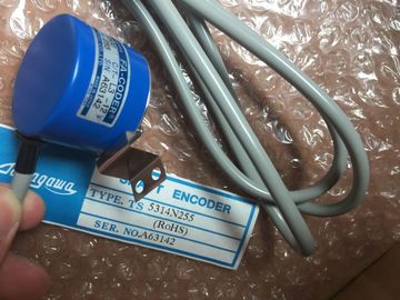
| Model Number: | TS5017N60 |
| Minimum Order Quantity: | 1pcs |
|---|---|
| Packaging Details: | carton |
| Delivery Time: | in stock |
| Payment Terms: | T/T, Western Union, MoneyGram |
| Supply Ability: | 100pcs/week |
| TAMAGAWA: | TAMAGAWA | Material: | Iron |
|---|---|---|---|
| Color: | Black | Japan: | Japan |
| Temperature: | 30-90 | Wire: | Wire |
| Dimension: | 90mm | TS5017N60: | TS5017N60 |
TS5017N60
| In the Devices and Networks portal, use the "Network view" to create the network connections between the devices in your project |
Creating a network connection" (Page 126) for more information.Table 10- 36 Configuring the CM 1243-5 (DP master) module and ET200 S DP slave PROFIBUS |
| To create the PROFIBUS connection, select the purple (PROFIBUS) box on the first device |
interfaces In a PROFIBUS network, each device is assigned a PROFIBUS address. This address can |
| Drag a line to the PROFIBUS box on the second device. Release the mouse button and your PROFIBUS connection is joined. Refer to "Device Configuration |
range from 0 through 127, with the following exceptions: |
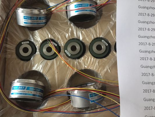
Guang Zhou Lai Jie Electric Co.,LTD
Please contact with “Tommy” for the price
TS3218N42
TS1508N77
TS3684N2E6
TS3653N12E6
TS3624N203E5
TS2013N191E26
TS3510N39E10
TS4509N1831E200
TS3218N5
TS1508N85
TS3684N3E8
TS3653N2E5
TS3624N22E4
TS2014N181E32
TS3653N95E8
TS4509N2002E200
TS3250E12
TS1526N55
TS3692N103
TS3624N2E3
TS3624N23E5
TS2014N311E32
TS3617N2E7
TS4509N2405E200
TS3275N125
TS1562N102
TS3692N41
TS3653N13E9
TS2014N18E32
TS2014N312E32
TS3617N3E10
TS4509N7000E100
TS3153N15E18
TS1567N132
TS3692N42
TS3653N2E6
Address 0: Reserved for network configuration and/or programming tools attached to the
bus
● Address 1: Reserved by for the first master
● Address 126: Reserved for devices from the factory that do not have a switch setting and
must be re-addressed through the network
● Address 127: Reserved for broadcast messages to all devices on the network and may
not be assigned to operational devices
Thus, the addresses that may be used for PROFIBUS operational devices are 2 through
125. In the Properties window, select the "PROFIBUS address" configuration entry. STEP 7
displays the PROFIBUS address configuration dialog, which is used to assign the
PROFIBUS address of the device.Name of the Subnet to which the device is connected. Click the "Add new subnet" button to create a
new subnet. "Not connected" is the default. Two connection types are possible:
The "Not connected" default provides a local connection.
A subnet is required when your network has two or more devices.
Address Assigned PROFIBUS address for the device
Highest address The highest PROFIBUS address is based on the active stations on the
PROFIBUS (for example, DP master). Passive DP slaves independently
have PROFIBUS addresses from 1 to 125 even if the highest PROFIBUS
address is set to 15, for example. The highest PROFIBUS address is
relevant for token forwarding (forwarding of the send rights), and the token
is only forwarded to active stations. Specifying the highest PROFIBUS
address optimizes the bus.
Parameters
Transmission rate Transmission rate of the configured PROFIBUS network: The PROFIBUS
transmission rates range from 9.6 Kbits/sec to 12 Mbits/sec. The
transmission rate setting depends on the properties of the PROFIBUS
nodes being used. The transmission rate should not be greater than the
rate supported by the slowest node.
The transmission rate is normally set for the master on the PROFIBUS
network, with all DP slaves automatically using that same transmission rate
(auto-baud).
Refer to "Distributed I/O (PROFINET, PROFIBUS, or AS-i)" (Page 274) for information on
how to use the distributed I/O instructions with these communication networks.
10.3.4 Diagnostic instructions
Refer to the "Diagnostics (PROFINET or PROFIBUS)": "Diagnostics instructions" (Page 297)
for information on how to use these instructions with these communication networksRefer to the "Diagnostics (PROFINET or PROFIBUS)": "Diagnostics events for distributed
I/O" (Page 297) for information on how to use this diagnostic information with these
communication networks. The AS-i master CM 1243-2 allows the attachment of an AS-i network to an S7-
1200 CPU.
The actuator/sensor interface, or AS-i, is a single master network connection system for the
lowest level in automation systems. The CM 1243-2 serves as the AS-i master for the
network. Using a single AS-i cable, sensors and actuators (AS-i slave devices) can be
connected to the CPU through the CM 1243-2. The CM 1243-2 handles all AS-i network
coordination and relays data and status information from the actuators and sensors to the
CPU through the I/O addresses assigned to the CM 1243-2. You can access binary or
analog values depending on the slave type. The AS-i slaves are the input and output
channels of the AS-i system and are only active when called by the CM 1243-2.
In the figure below, the is an AS-i master controlling AS-i operator panel and I/O
module digital/analog slave devices.The AS-i master CM 1243-2 is integrated into the automation system as a
communication module.
You can find detailed information on the AS-i master CM 1243-2 in the "AS-i master CM
1243-2 and AS-i data decoupling unit DCM 1271 for SIMATIC " Manual Use the hardware catalog to add AS-i master CM1243-2 modules to the CPU. These
modules are connected to the left side of the CPU, and a maximum of three AS-i master
CM1243-2 modules can be used. To insert a module into the hardware configuration, select
the module in the hardware catalog and either double-click or drag the module to the
highlighted slot. Use the hardware catalog to add AS-i slaves as well. For example, to add an "I/O module,
compact, digital, input" slave, in the Hardware Catalog, expand the following containers:
● Field devices
● AS-Interface slaves
Next, select "3RG9 001-0AA00" (AS-i SM-U, 4DI) from the list of part numbers, and add the
"I/O module, compact, digital, input" slave as shown in the figure below. After you configure the AS-i master CM1243-2, you are now ready to configure your network
connections.