 |
| Place of Origin: | Japan |
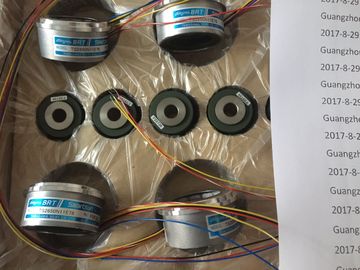
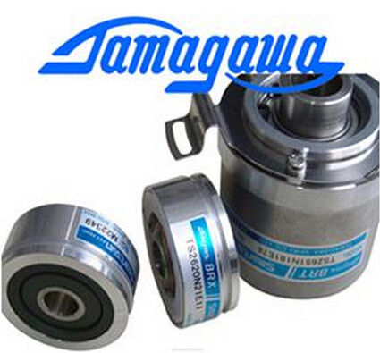
| Brand Name: | Tamagawa |
| Certification: | CE |
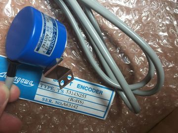
| Model Number: | TS2014N311E32 |
| Minimum Order Quantity: | 1pcs |
|---|---|
| Packaging Details: | carton |
| Delivery Time: | in stock |
| Payment Terms: | T/T, Western Union, MoneyGram |
| Supply Ability: | 100pcs/week |
| Tamagawa: | Tamagawa | TS2014N311E32: | TS2014N311E32 |
|---|---|---|---|
| Japan: | Japan | Material: | Iron |
| Color: | Black | Temperature: | 30-90 |
| Dimension: | 60mm | Wire: | Wire |
TS2014N311E32
| 081 The source area is larger than the destination area. The destination area is completely filled and the | 82B1 Missing source data block |
| remaining bytes of the source are ignored. | 82C0 The source DB is being edited by another statement or a communication function. |
| 8251 Source data block type error | 551 Destination data block type error |
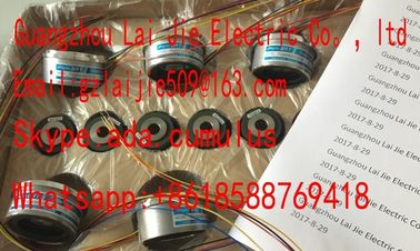
Guang Zhou Lai Jie Electric Co.,LTD
Please contact with “Tommy” for the price
TS4603N1000E100
TS3617N2E5
TS3617N40E3
TS4515N2405E200
TS3617N1E3
TS2014N185E32
TS4602N1000E200
TS4603N1000E200
TS3617N2E6
TS5214N566
TS5205N450
TS5213N551
TS5208N122
TS5208N23
TS5778N171
TS5210N53
TS5320N510
TS5000N632
TS5212N510
TS5213N510
TS5312N616
TS208N101
TS5208N130
TS5213N530
TS5013N68
TS5214N566
TS5200N500
TS5305N616
TS5669N220
TS5214N564
TS5246N158
TS5667N650
TS5213N551
TS5668N20
TS5667N120
TS5667N420
TS5246N160
TS5312N512
TS5208N122
TS5641N151
TS5270N15
TS5308N616
TS5213N510
TS2014N181E32
TS5308N616
TS3462N1E76
TS5214N561
TS5214N510
TS2014N182E32
TS3653N2E5
TS5320N510
TS5016N-60
TS5016N60
TS2651N111E78
TS2014N181E32
TS2651N131E78
TS2651N141E78
TS5214N566
85B1 Missing destination data block
85C0 The destination DB is being edited by another statement or a communication function.
80C3 More than 50 READ_DBL or 50 WRIT_DBL statements are currently queued for executionArea too small for input
8023 Area too small for output
8024 Illegal input area
8025 Illegal output area
8028 Illegal input bit assignment
8029 Illegal output bit assignment
8030 Output area is a read-only DB.
803A DB does not exist.
1 If one of these errors occurs when a code block is executed the the CPU goes to STOP mode, unless you use the
GetError or GetErrorID instructions within that code block and create a programmed reaction to the error. Each CTRL_HSC instruction uses a structure stored in
a DB to maintain data. You assign the DB when the
CTRL_HSC instruction is placed in the editor. HSC identifier
DIR1, 2 IN Bool 1 = Request new direction
CV1 IN Bool 1 = Request to set new counter value
RV1 IN Bool 1= Request to set new reference value
PERIOD1 IN Bool 1 = Request to set new period value
(only for frequency measurement mode)
NEW_DIR IN Int New direction: 1= forward, -1= backward
NEW_CV IN DInt New counter value
NEW_RV IN DInt New reference value
NEW_PERIOD IN Int New period value in seconds: 0.01, 0.1, or 1
(only for frequency measurement mode)
BUSY3 OUT Bool Function is busy
STATUS OUT Word Execution condition code
1 If an update of a parameter value is not requested, then the corresponding input values are ignored.
2 The DIR parameter is only valid if the configured counting direction is set to "User program (internal direction control)".
You determine how to use this parameter in the HSC device configuration.
3 For an HSC on the CPU or on the SB, the BUSY parameter always has a value of 0.You configure the parameters for each HSC in the device configuration for the CPU:
counting mode, I/O connections, interrupt assignment, and operation as a high-speed
counter or as a device to measure pulse frequency.
Some of the parameters for the HSC can be modified by your user program to provide
program control of the counting process:
● Set the counting direction to a NEW_DIR value
● Set the current count value to a NEW_CV value
● Set the reference value to a NEW_RV value
Set the period value (for frequency measurement mode) to a NEW_PERIOD value
If the following Boolean flag values are set to 1 when the CTRL_HSC instruction is executed,
the corresponding NEW_xxx value is loaded to the counter. Multiple requests (more than
one flag is set at the same time) are processed in a single execution of the CTRL_HSC
instruction.
● DIR = 1 is a request to load a NEW_DIR value, 0 = no change
● CV = 1 is a request to load a NEW_CV value, 0 = no change
● RV = 1 is a request to load a NEW_RV value, 0 = no change
● PERIOD = 1 is a request to load a NEW_PERIOD value, 0 = no change
The CTRL_HSC instruction is typically placed in a hardware interrupt OB that is executed
when the counter hardware interrupt event is triggered. For example, if a CV=RV event
triggers the counter interrupt, then a hardware interrupt OB code block executes the
CTRL_HSC instruction and can change the reference value by loading a NEW_RV value.
The current count value is not available in the CTRL_HSC parameters. The process image
address that stores the current count value is assigned during the hardware configuration of
the high-speed counter. You may use program logic to directly read the count value. The
value returned to your program will be a correct count for the instant in which the counter
was read. The counter will continue to count high-speed events. Therefore, the actual count
value could change before your program completes a process using an old count value.
Condition codes: In the case of an error, ENO is set to 0, and the STATUS output contains a
condition code.
Table 9- 3 STATUS values (W#16#)
STATUS Description
0 No error
80A1 HSC identifier does not address a HSC
80B1 Illegal value in NEW_DIR
80B2 Illegal value in NEW_CV
80B3 Illegal value in NEW_RV
80B4 Illegal value in NEW_PERIOD
80C0 Multiple access to the high-speed counter
80D0 High-speed counter (HSC) not enabled in CPU hardware configuration The high-speed counter (HSC) counts events that occur faster than the OB execution rate. If
the events to be counted occur within the execution rate of the OB, you can use CTU, CTD,
or CTUD counter instructions. If the events occur faster than the OB execution rate, then use
the HSC. The CTRL_HSC instruction allows your user program to programmatically change
some of the HSC parameters.
For example: You can use the HSC as an input for an incremental shaft encoder. The shaft
encoder provides a specified number of counts per revolution and a reset pulse that occurs
once per revolution. The clock(s) and the reset pulse from the shaft encoder provide the
inputs to the HSC.
The HSC is loaded with the first of several presets, and the outputs are activated for the time
period where the current count is less than the current preset. The HSC provides an interrupt
when the current count is equal to preset, when reset occurs, and also when there is a
direction change.
As each current-count-value-equals-preset-value interrupt event occurs, a new preset is
loaded and the next state for the outputs is set. When the reset interrupt event occurs, the
first preset and the first output states are set, and the cycle is repeated.
Since the interrupts occur at a much lower rate than the counting rate of the HSC, precise
control of high-speed operations can be implemented with relatively minor impact to the scan
cycle of the CPU. The method of interrupt attachment allows each load of a new preset to be