 |
| Place of Origin: | Japan |
| Brand Name: | Tamagawa |
| Certification: | CE |
| Model Number: | TS2650N11E78 |
| Minimum Order Quantity: | 1pcs |
|---|---|
| Packaging Details: | carton |
| Delivery Time: | in stock |
| Payment Terms: | T/T, MoneyGram, Western Union |
| Supply Ability: | 100pcs/week |
| TAMAGAWA: | TAMAGAWA | Material: | Iron |
|---|---|---|---|
| Color: | Black | Japan: | Japan |
| Temperature: | 20-90 | TS2650N11E78: | TS2650N11E78 |
| Wire: | Wire |
TS2650N11E78
| The PROFINET port on the CPU does not contain an Ethernet switching device. |
functionality is built into the CPU, you can use either a standard or crossover Ethernet cable |
| The rack-mounted CSM1277 4-port Ethernet switch can be used to connect your CPUs and HMI devices |
System diagnostics Establishing the hardware communications connection A PROFINET interface establishes the physical connection between an HMI and a CPU. Since AutoCross-Over |
| The HMI can read/write data to the CPU. ● Messages can be triggered, based upon i |
for the interface. An Ethernet switch is not required to connect an HMI and a CPU. Refer to "Communication with a programming device: Establishing the hardware communications |
Guang Zhou Lai Jie Electric Co.,LTD
Please contact with “Tommy” for the price
TS3653N2E5
TS5320N510
TS5016N-60
TS5016N60
TS2651N111E78
TS2014N181E32
TS2651N131E78
TS2651N141E78
TS5214N566
TS5205N450
TS5308N616
TS3462N1E76
48-2500P8-L6-5V
TS5214N561
TS5214N510
TS2014N182E32
TS3653N2E5
TS5320N510
TS5016N-60
TS5016N60
TS2651N111E78
TS2014N181E32
TS5013N60,
TS5013N61,
TS5016N60,
TS5017N60,
TS5013N68,
TS5
013N69
TS5013N60
TS5016N60
TS5013N60
TS5016N60
TS5017N60
TS5013N68
TS5013N69
TS2014N181E32
TS2014N311E32
TS2650N11E78
TS2650N1E78
TS5081N1
TS5084N250
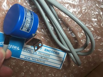
TS5314N255
TS5303N510
TS5622N131
TS1616N200
TS1501N13
TS5641N154
TS5205N454
TS5668N20
TS5667N120
TS5667N420
TS5308N616
TS3462N1E76
TS5214N561
TS5214N510
TS2014N182E32
TS3653N2E5
TS5320N510
TS5016N60
TS5016N60
TS2651N111E78
connection" (Page 460) for more information.
2 Configuring the devices
Refer to "Communication with a programming device: Configuring the devices" (Page 461) for more
information.
3 Configuring the logical network connections between an HMI and a CPU
Refer to "HMI-to-PLC communication: Configuring the logical network connections between two devices"
(Page 463) for more information.
4 Configuring an IP address in your project
Use the same configuration process; however, you must configure IP addresses for the HMI and the CPU.
Refer to "Device configuration: Configuring an IP address for a CPU in your project" (Page 136) for more
information.
5 Testing the PROFINET network
You must download the configuration for each CPU and HMI device.
Refer to "Device configuration: Testing the PROFINET network" (Page 139) for more information. To create a PROFINET connection, click the green (PROFINET) box on the first device, and
drag a line to the PROFINET box on the second device. Release the mouse button and your
PROFINET connection is joined.
Refer to "Device Configuration: Creating a network connection" (Page 126) for more
information.
A CPU can communicate with another CPU on a
network by using the TSEND_C and TRCV_C
instructions.
Consider the following when setting up communications between two CPUs:
● Configuration/Setup: Hardware configuration is required.
● Supported functions: Reading/Writing data to a peer CPU
● No Ethernet switch is required for one-to-one communications; an Ethernet switch is
required for more than two devices in a network.Establishing the hardware communications connection
A PROFINET interface establishes the physical connection between two CPUs. Since Auto-Cross-Over
functionality is built into the CPU, you can use either a standard or crossover Ethernet cable for the
interface. An Ethernet switch is not required to connect the two CPUs.
Refer to "Communication with a programming device: Establishing the hardware communications
connection" (Page 460) for more information.
2 Configuring the devices
You must configure two CPUs in your project.
Refer to "Communication with a programming device: Configuring the devices" (Page 461) for more
information.
3 Configuring the logical network connections between two CPUs
Refer to "PLC-to-PLC communication: Configuring logical network connections between two devices"
(Page 465) for more information.
4 Configuring an IP address in your project
Use the same configuration process; however, you must configure IP addresses for two CPUs (for
example, PLC_1 and PLC_2).
Refer to "Device configuration: Configuring an IP address for a CPU in your project" (Page 136) for more
information. Configuring transmit (send) and receive parameters
You must configure TSEND_C and TRCV_C instructions in both CPUs to enable communications between
them.
Refer to "Configuring communications between two CPUs: Configuring transmit (send) and receive
parameters" (Page 465) for more information.
6 Testing the PROFINET network
You must download the configuration for each CPU.
Refer to "Device configuration: Testing the PROFINET network" (Page 139) for more information.
After you configure the rack with the CPU, you are now ready to configure your network
connections.
In the Devices and Networks portal, use the "Network view" to create the network
connections between the devices in your project. First, click the "Connections" tab, and then
select the connection type with the dropdown, just to the right (for example, an ISO on TCP
connection).
To create a PROFINET connection, click the green (PROFINET) box on the first device, and
drag a line to the PROFINET box on the second device. Release the mouse button and your
PROFINET connection is joined.
Refer to "Device Configuration: Creating a network connection" (Page 126) for more
information.
10.2.5.2 Configuring the Local/Partner connection path between two devices
Configuring General parameters
You specify the communication parameters in the "Properties" configuration dialog of the
communication instruction. This dialog appears near the bottom of the page whenever you
have selected any part of the instruction.
Refer to "Device configuration: Configuring the Local/Partner connection path (Page 127)"
for more information.
In the "Address Details" section of the Connection parameters dialog, you define the TSAPs
or ports to be used. The TSAP or port of a connection in the CPU is entered in the "Local
TSAP" field. The TSAP or port assigned for the connection in your partner CPU is entered
under the "Partner TSAP" field.
10.2.5.3 Configuring transmit (send) and receive parameters
Communication blocks (for example, TSEND_C and TRCV_C) are used to establish
connections between two CPUs. Before the CPUs can engage in PROFINET
communications, you must configure parameters for transmitting (or sending) messages and
receiving messages. These parameters dictate how communications operate when
messages are being transmitted to or received from a target device. The TSEND_C instruction (Page 432) creates a communications connection to a partner
station. The connection is set up, established, and automatically monitored until it is
commanded to disconnect by the instruction. The TSEND_C instruction combines the
functions of the TCON, TDISCON and TSEND instructions.
From the Device configuration in STEP 7, you can configure how a TSEND_C instruction
transmits data. To begin, you insert the instruction into the program from the
"Communications" folder in the "Instructions" task card. The TSEND_C instruction is
displayed, along with the Call options dialog where you assign a DB for storing the
parameters of the instruction. You can assign tag memory locations to the inputs and