|
| Place of Origin: | Japan |
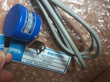
| Brand Name: | Tamagawa |
| Certification: | CE |
| Model Number: | TS5081N1 |
| Minimum Order Quantity: | 1pcs |
|---|---|
| Packaging Details: | carton |
| Delivery Time: | in stock |
| Payment Terms: | T/T, Western Union, MoneyGram |
| Supply Ability: | 100pcs/week |
| TAMAGAWA: | TAMAGAWA | TS5081N1: | TS5081N1 |
|---|---|---|---|
| Japan: | Japan | COLOR: | BLACK |
| Material: | Iron | Temperature: | 30-80 |
| Wire: | Wire | Dimension: | 40mm |
TS5081N1
| Corresponding structure Type shown in FB interface |
Under Static, locate the counter structure that was just created for you. Under Static, locate the counter structure that was just created for you. |
| INT IEC_Counter SINT IEC_SCounter DINT IEC_DCounter UINT IEC_UCounter USINT IEC_USCounter UDINT IEC_UDCounter |
In the Retain column for this counter structure, change the selection to "Retain". Whenever this FB is called later from another program block, |
| If necessary, open the FB interface editor (may have to click on the small arrow to expand the view). |
an instance DB will be created with this interface definition which contains the counter structure marked as retentive. If the FB was created with the "Symbolic access only" box not checked: 1. Open the FB for edit. |
Guang Zhou Lai Jie Electric Co.,LTD
Please contact with “Tommy” for the price
TS5013N60
TS5013N61
TS5016N60
TS5013N63
TS5013N64
TS5016N61
TS5013N66
TS5016N63
TS5016N64
TS5017N60
TS5019N60
TS5420N60
TS5778N155
TS5013N68
TS5013N69
TS5208N131
TS5208N23
TS2025N471E69
TS2014N181E32
TS5208N111E78
TS5208N141E78
TS5631N224
PULSE
GENERATOR
RP-182
750PPR
PULSE
GENERATOR
RP-182
1500PPR
PULSE
Place the counter instruction at the desired location in the FB.
3. When the Call options dialog appears, click on the multi instance icon. The multi instance
option is only available if the instruction is being placed into an FB.
4. In the Call options dialog, rename the counter if desired.
5. Click OK. The counter instruction appears in the editor with type INT for the preset and
count value, and the IEC_COUNTER structure appears in the FB Interface under Static.
6. If desired, change the type in the counter instruction from INT to one of the other types.
The counter structure will change correspondingly.
Type shown in counter instruction (for preset
and count values)
Corresponding structure Type shown in FB
interface
INT IEC_Counter
SINT IEC_SCounter
DINT IEC_DCounter
UINT IEC_UCounter
USINT IEC_USCounter
UDINT IEC_UDCounter
1. Open the block that will use this FB.
2. Place this FB at the desired location. Doing so results in the creation of an instance data
block for this FB.
3. Open the instance data block created when you placed the FB in the editor.
4. Under Static, locate the counter structure of interest. In the Retain column for this counter
structure, check the box to make this structure retentive. Compares two values of the same data type. When the
LAD contact comparison is TRUE, then the contact is
activated. When the FBD box comparison is TRUE,
then the box output is TRUE. SInt, Int, DInt, USInt, UInt, UDInt, Real, LReal, String, Char,
Time, DTL, Constant
Tests whether an input value is in or out of a specified value range.
If the comparison is TRUE, then the box output is TRUE. The input parameters MIN, VAL, and MAX must be the same data type.
● The IN_RANGE comparison is true if: MIN <= VAL <= MAX
● The OUT_RANGE comparison is true if: VAL < MIN or VAL > MAX
Tests whether an input data reference is a valid real
number according to IEEE specification 754For LAD and FBD: When the LAD contact is TRUE, the contact is activated and passes power flow. When the FBD box
is TRUE, then the box output is TRUE. A Real or LReal value is invalid if it is +/- INF (infinity), NaN (Not a Number), or if it is a denormalized value. A
denormalized value is a number very close to zero. The CPU substitutes a zero for a denormalized value in calculations. Use the
standard SCL
math
expressions to
create the
equation.
The CALCULATE instruction lets you create a math function that
operates on inputs (IN1, IN2, .. INn) and produces the result at OUT,
according to the equation that you define.
Select a data type first. All inputs and the output must be the same
data type.
To add another input, click the icon at the last input. IN1, IN2, ..INn SInt, Int, DInt, USInt, UInt, UDInt, Real, LReal, Byte, Word, DWord
OUT SInt, Int, DInt, USInt, UInt, UDInt, Real, LReal, Byte, Word, DWord
1 The IN and OUT parameters must be the same data type (with implicit conversions of the input parameters). For