|
| Place of Origin: | Japan |
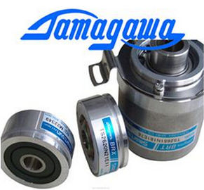
| Brand Name: | Tamagawa |
| Certification: | CE |
| Model Number: | TS2014N182E32 |
| Minimum Order Quantity: | 1pcs |
|---|---|
| Packaging Details: | carton |
| Delivery Time: | in stock |
| Payment Terms: | T/T, Western Union, MoneyGram |
| Supply Ability: | 100pcs/week |
| TAMAGAWA: | TAMAGAWA | TS2014N182E32: | TS2014N182E32 |
|---|---|---|---|
| Material: | Iron | Color: | Black |
| Temperature: | 30-90 | Dimension: | 80mm |
| Wire: | Wire | Japan: | Japan |
TS2014N182E32![]()
![]()
![]()
| WRREC instruction (Page 275): You can transfer a data record with the number INDEX to a module or device defined by ID. |
DPWR_DAT instruction (Page 284): You must write consistent data areas greater than 64 bytes to a module or device with the DPWR_DAT instruction. |
| RALRM instruction (Page 278): You can receive an interrupt with all corresponding information from a module or device and supply this information to its output parameters. |
The DPNRM_DG instruction (Page 286) can only be used with PROFIBUS. You can read the current diagnostic data of a DP slave in the format specified by EN 50 170 Volume 2, |
| DPRD_DAT instruction (Page 284): You must read consistent data areas greater than 64 bytes from a module or device with the DPRD_DAT instruction. |
PROFIBUS. Use the RDREC instruction to read a data record with the number INDEX from the component addressed by the ID, such as a central rack or a distributed component (PROFIBUS DP or PROFINET IO). |
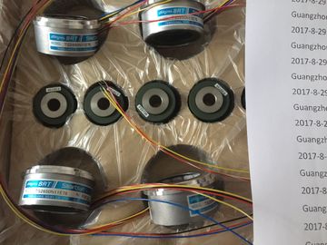
Guang Zhou Lai Jie Electric Co.,LTD
Please contact with “Tommy” for the price
TS3624N2E4
TS3624N3E5
TS3624N3E6
TS3630N1E1
TS3630N1E2
TS3630N2E3
TS3630N2E4
TS3630N3E5
TS3630N3E6
TS3630N1303E9
TS3630N1306
TS3630N11E1
TS3630N11E2
TS3630N12E3
TS3630N12E4
TS3630N13E5
TS3630N13E6
FA-CODER
TS5214N566
TS5205N450
TS5205N454
TS5205
N450
TS5205
N454
TS5205N452
TS5205
N452
TS5207
TS5208
TS5212
TS5213
TS5214
Assign the maximum number of bytes to
read in MLEN. The selected length of the
target area RECORD should have at
least the length of MLEN bytes.REQ = 1: Transfer data record
ID IN HW_IO (Word) Logical address of the DP slave/PROFINET IO component
(module or submodule):
For an output module, bit 15 must be set (for example, for
address 5: ID:= DW#16#8005).
For a combination module, the smaller of the two addresses
should be specified.
Note: The device ID can be determined in one of two ways:
By making the following "Network view" selections:
– Device (gray box)
– "Properties" of the device
– "Hardware identifier"
Note: Not all devices display their Hardware identifiers,
however.
By making the following "Project tree" menu selections:
– PLC tags
– Default tag table
– System constants tab
All configured device Hardware identifiers are displayed.
INDEX IN Byte, Word, USInt,
UInt, SInt, Int, DInt
Data record number
MLEN IN Byte, USInt, UInt Maximum length in bytes of the data record information to be
fetched (RDREC)
VALID OUT Bool New data record was received and valid (RDREC). The VALID
bit is TRUE for one scan, after the last request was completed
with no error.
DONE OUT Bool Data record was transferred (WRREC). The DONE bit is TRUE
for one scan, after the last request was completed with no error.
BUSY OUT Bool BUSY = 1: The read (RDREC) or write (WRREC) process is
not yet terminated.
BUSY = 0: Data record transmission is completed.
ERROR OUT Bool ERROR = 1: A read (RDREC) or write (WRREC) error has
occurred. The ERROR bit is TRUE for one scan, after the last
request was terminated with an error. The error code value at
the STATUS parameter is valid only during the single scan
where ERROR = TRUE.
STATUS OUT DWord Block status or error information
LEN OUT (RDREC)
IN (WRREC)
UInt Length of the fetched data record information (RDREC)
Maximum byte length of the data record to be transferred