 |
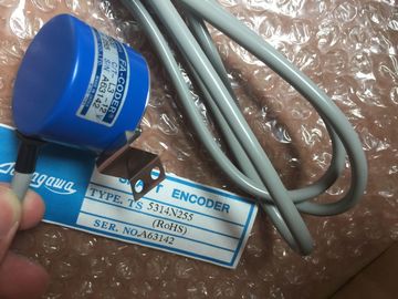
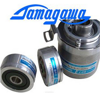
| Place of Origin: | Japan |
| Brand Name: | Tamagawa |
| Certification: | CE |
| Model Number: | TS5016N60 |
| Minimum Order Quantity: | 1pcs |
|---|---|
| Packaging Details: | carton |
| Delivery Time: | in stock |
| Payment Terms: | T/T, Western Union, MoneyGram |
| Supply Ability: | 100pcs/week |
| TAMAGAWA: | TAMAGAWA | TS5016N60: | TS5016N60 |
|---|---|---|---|
| Material: | Iron | Color: | Black |
| Temperature: | 20-90 | Japan: | Japan |
| Dimension: | 40mm | Wire: | Wire |
TS5016N60
| BUSY3 OUT Bool Function is busySTATUS OUT Word Execution condition code | The DIR parameter is only valid if the configured counting direction is set to "User program (internal direction control)". |
| STATUS OUT Word Execution condition code If an update of a parameter value is not requested, then the corresponding input values are ignored. | You determine how to use this parameter in the HSC device configuration. |
| If an update of a parameter value is not requested, then the corresponding input values are ignored. | 3 For an HSC on the CPU or on the SB, the BUSY parameter always has a value of 0.You configure the parameters for each HSC in the device configuration for the CPU: |
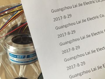
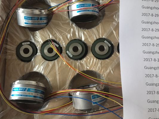
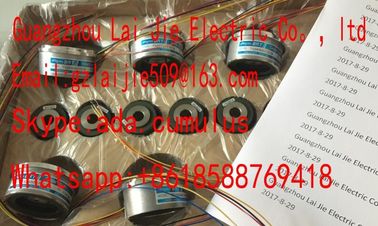
Guang Zhou Lai Jie Electric Co.,LTD
Please contact with “Tommy” for the price
TS2014N181E32
TS-5208N130
TS5207N76
TS5246N160
TS5312N616-2000C-T
TS5312N616
TS5217N530
DIH35-5000C/T-P8-L6-5V
OIH100-1024C/T-P2-12V
TS5233N430
DIH48-6000C/T-P8-L6-5V
TS5246N430
TS1857N112
TS5213N551
TS5214N364
TS5312N512-2000C/TOSE.5KN-6-12-108
TS5146N11
BKO-NC6214
TS5214N500
48-2500PA-L6-5V
TS5205N4540IH60-8192C/T-P8-L6-5V
TS3699N172
TS3653N3E8
1510N122
TS3653N1E2
TS5667N120
TS3624N2E3
TS3738N1E7
TS2151N1E45
TS3699N232
TS3653N3E9
2000144
TS3653N2E4
counting mode, I/O connections, interrupt assignment, and operation as a high-speed
counter or as a device to measure pulse frequency.
Some of the parameters for the HSC can be modified by your user program to provide
program control of the counting process:
● Set the counting direction to a NEW_DIR value
● Set the current count value to a NEW_CV value
● Set the reference value to a NEW_RV value
● Set the period value (for frequency measurement mode) to a NEW_PERIOD value
If the following Boolean flag values are set to 1 when the CTRL_HSC instruction is executed,
the corresponding NEW_xxx value is loaded to the counter. Multiple requests (more than
one flag is set at the same time) are processed in a single execution of the CTRL_HSC
instruction.
● DIR = 1 is a request to load a NEW_DIR value, 0 = no change
● CV = 1 is a request to load a NEW_CV value, 0 = no change
● RV = 1 is a request to load a NEW_RV value, 0 = no change
● PERIOD = 1 is a request to load a NEW_PERIOD value, 0 = no change
The CTRL_HSC instruction is typically placed in a hardware interrupt OB that is executed
when the counter hardware interrupt event is triggered. For example, if a CV=RV event
triggers the counter interrupt, then a hardware interrupt OB code block executes the
CTRL_HSC instruction and can change the reference value by loading a NEW_RV value.
The current count value is not available in the CTRL_HSC parameters. The process image
address that stores the current count value is assigned during the hardware configuration of
the high-speed counter. You may use program logic to directly read the count value. The
value returned to your program will be a correct count for the instant in which the counter
was read. The counter will continue to count high-speed events. Therefore, the actual count
value could change before your program completes a process using an old count value.
Condition codes: In the case of an error, ENO is set to 0, and the STATUS output contains a
condition code.
Table 9- 3 STATUS values (W#16#)
STATUS Description
0 No error
80A1 HSC identifier does not address a HSC
80B1 Illegal value in NEW_DIR
80B2 Illegal value in NEW_CV
80B3 Illegal value in NEW_RV
80B4 Illegal value in NEW_PERIOD
80C0 Multiple access to the high-speed counter
80D0 High-speed counter (HSC) not enabled in CPU hardware configuration The high-speed counter (HSC) counts events that occur faster than the OB execution rate. If
the events to be counted occur within the execution rate of the OB, you can use CTU, CTD,
or CTUD counter instructions. If the events occur faster than the OB execution rate, then use
the HSC. The CTRL_HSC instruction allows your user program to programmatically change
some of the HSC parameters.
For example: You can use the HSC as an input for an incremental shaft encoder. The shaft
encoder provides a specified number of counts per revolution and a reset pulse that occurs
once per revolution. The clock(s) and the reset pulse from the shaft encoder provide the
inputs to the HSC.
The HSC is loaded with the first of several presets, and the outputs are activated for the time
period where the current count is less than the current preset. The HSC provides an interrupt
when the current count is equal to preset, when reset occurs, and also when there is a
direction change.
As each current-count-value-equals-preset-value interrupt event occurs, a new preset is
loaded and the next state for the outputs is set. When the reset interrupt event occurs, the
first preset and the first output states are set, and the cycle is repeated.
Since the interrupts occur at a much lower rate than the counting rate of the HSC, precise
control of high-speed operations can be implemented with relatively minor impact to the scan
cycle of the CPU. The method of interrupt attachment allows each load of a new preset to be
performed in a separate interrupt routine for easy state control. (Alternatively, all interrupt
events can be processed in a single interrupt routine.) The high-speed counter (HSC) counts events that occur faster than the OB execution rate. If
the events to be counted occur within the execution rate of the OB, you can use CTU, CTD,
or CTUD counter instructions. If the events occur faster than the OB execution rate, then use
the HSC. The CTRL_HSC instruction allows your user program to programmatically change
some of the HSC parameters.
For example: You can use the HSC as an input for an incremental shaft encoder. The shaft
encoder provides a specified number of counts per revolution and a reset pulse that occurs
once per revolution. The clock(s) and the reset pulse from the shaft encoder provide the
inputs to the HSC.
The HSC is loaded with the first of several presets, and the outputs are activated for the time
period where the current count is less than the current preset. The HSC provides an interrupt
when the current count is equal to preset, when reset occurs, and also when there is a
direction change.