 |
| Place of Origin: | Japan |
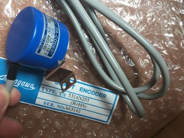
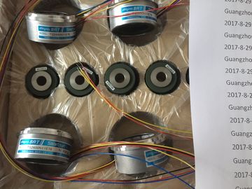
| Brand Name: | Tamagawa |
| Certification: | CE |
| Model Number: | TS2651N11E78 |
| Minimum Order Quantity: | 1pcs |
|---|---|
| Packaging Details: | carton |
| Delivery Time: | in stock |
| Payment Terms: | T/T, Western Union, MoneyGram |
| Supply Ability: | 100pcs/week |
| TAMAGAWA: | TAMAGAWA | TS2651N11E78: | TS2651N11E78 |
|---|---|---|---|
| Material: | Iron | Color: | Black |
| Temperature: | 20-90 | Dimension: | 60mm |
| Wire: | Wire | Japan: | Japan |
TS2651N11E78
| DeviceStates instruction (Page 299): You can retrieve the operational states for a distributed I/O device within an I/O subsystem. |
8.5.2 Diagnostic events for distributed I/O Note |
| ModuleStates instruction (Page 301): You can retrieve the operational states for the modules in a distributed I/O device. |
ith a PROFIBUS IO system, after a download or power cycle, the CPU will go to RUN |
| LED instruction (Page 298): You can read the state of the LEDs for a distributed I/O device |
mode unless the hardware compatibility is set to allow acceptable substitute modules |
Guang Zhou Lai Jie Electric Co.,LTD
Please contact with “Tommy” for the price
OAS66
TS1857N16EP
TS3667N2E5
TS5016N63
TS3643N2
TS5308N510
TS20E12
TS4503N2202E200
TS3134N21
TS3667N2E6
TS5016N64
TS3643N212E5
TS530N33E9
TS2151N121E9
TS4503N2036E501
TS3134N22
OIS1000CT3L5V108
TS3667N3E7
TS5017N60
TS3643N233E8
TS5312-N250
TS2151N141E9
TS4506N1202E200
TS3134N317
OSE10243158
TS3667N3E8
TS5019N60
TS3653N11E2
TS5313N122
TS2228N33E1
(Page 123) and one or more modules is missing or is not an acceptable substitute for the
configured module. As shown in the following table, the CPU supports diagnostics that can be configured for the
components of the distributed I/O system. Each of these errors generates a log entry in the
diagnostic buffer.
Table 8- 101 Handling of diagnostic events for PROFINET and PROFIBUS I/O access error example cause: A module that has been removed.
2 Peripheral access error example cause: Acyclic communication to a submodule that is not communicating.
Use the GET_DIAG instruction (Page 302) for each station to obtain the diagnostic
information. This will allow you to programmatically handle the errors encountered on the
device and if desired take the CPU to STOP mode. This method requires you to specify the
hardware device from which to read the status information.
The GET_DIAG instruction uses the "L address" (LADDR) of the station to obtain the health
of the entire station. This L Address can be found within the Network Configuration view and
by selecting the entire station rack (entire gray area), the L Address is shown in the
Properties Tab of the station. You can find the LADDR for each individual module either in
the properties for the module (in the device configuration) or in the default tag table for the
CPU.Use the LED instruction to read the state of the LEDs on a CPU or
interface. The specified LED state is returned by the RET_VAL
output. DeviceStates retrieves the I/O device operational
states of an I/O subsystem. After execution, the
STATE parameter contains the error state of each
I/O device in a bit list (for the assigned LADDR and
MODE). This information corresponds with the
device status seen in the STEP 7 diagnostics view. Logical address: (Identifier for the I/O system)
MODE IN UInt Status type:
1: Configuration of device is active or not yet complete.
2: Device defective
3: Device disabled
4: Device exists
RET_VAL OUT Int Execution condition code
STATE1 InOut Variant Buffer that receives the error status of each device: The data type
that you choose for the STATE parameter can be any bit type
(Bool, Byte, Word, or DWord) or an array of a bit type
Summary bit: Bit 0 =1, if one of the state bits of the I/O devices
is 1
State bit: State of I/O device with station number n according to
the selected MODE. For example, MODE = 2 and bit 3 = 1
means station 3 is faulty.
1 For PROFIBUS-DP, the length of the status information is 128 bits. For PROFINET I/O, the length is 1024 bits.
After execution, the STATE parameter contains the error state of each I/O device as a bit list
(for the assigned LADDR and MODE)No error
8091 LADDR does not exist.
8092 LADDR does not address an I/O system.
8093 Invalid data type assigned for STATE parameter: Valid data types are (Bool, Byte, Word, or
Dword), or an array of (Bools, Bytes, Words, or Dwords)
80Bx DeviceStates instruction not supported by the CPU for this LADDR.
8452 The complete state data is too large for the assigned STATE parameter. The STATE buffer
contains a partial result. ModuleStates retrieves the operational states
of I/O modules. After execution, the STATE
parameter contains the error state of each I/O
module in a bit list (for the assigned LADDR
and MODE). This information corresponds
with the module status seen in the STEP 7
diagnostics view.
Logical address (Identifier for the I/O modules)
MODE IN UInt Status type:
1: Configuration of module is active or not yet complete.
2: Module defective
3: Module disabled
4: Module exists